Any ideas ? SPI talking to MAX11633 ADC

Status
Not open for further replies.

tf3t

Member
Hi all

So I'm copying code from a PIC project - so I have the data how to talk to the MAX.

Nothing working ;)
Screen Shot 2018-04-14 at 13.34.20.jpg


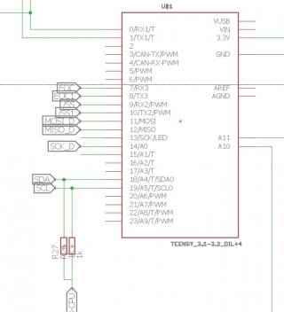
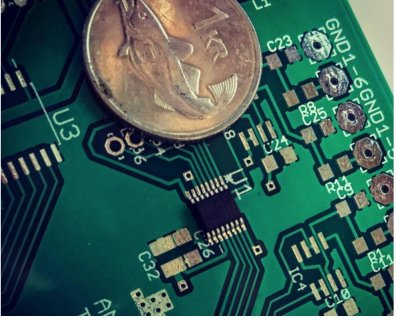
As I have this now soldered my brand new PCB fresh from China - I can't change anything, but I have confirmed the pins are connected correctly

With two exceptions:
SCK is on pin 14, not 13 - was hurrying to get the PCB design out, saw that the LED is connected to pin 13 - so I picked the alternative pin
CS was put on a pin 10 - that should be ok
then I have a input pin that should go low when conversion is done

here is the code - please let me know if you see something obvious - else I need to get a logic analyzer and see what is going on
And note this is the first time I write directly to a SPI device, just been using libraries for LCD etc.

and yes, " if(digitalRead(EOC) == 0)" never gets true - If I just read it I get 0.

Running the Teensy at 96Mhz -
from the datasheet: " 10MHz 3-Wire SPI-/QSPI-/MICROWIRE-Compatible interface"


Code:
// 
//  MAX MAX11626–MAX11629/
//  MAX11632/MAX11633
//  Test code
//  - not working 

#include <SPI.h>

#define SS1 10
#define EOC 8

#define MAXCHANNEL_ADCA 7


void setup() {
 
 Serial.begin(9600);
 
 pinMode(SS1,OUTPUT);
 pinMode(EOC,INPUT);


 digitalWrite(SS1, HIGH);
 delayMicroseconds(50);

 
	 SPI.setSCK(14);
	 SPI.begin();
	 
	 delay(100);
	 SPI.beginTransaction (SPISettings (4000000, MSBFIRST, SPI_MODE0));

	 digitalWrite(SS1, LOW);

	SPI.transfer(0b01101000);   // setup register
	delayMicroseconds(1);
	SPI.transfer(0b00110100);   // Averaging register, 8 measurments, 
	delayMicroseconds(1);
	SPI.transfer(0b00011000);   // reset FIFO
	SPI.transfer(0b10000000 | ((MAXCHANNEL_ADCA-1)<<3));  // Start conversion
	 
	 
	digitalWrite(SS1, HIGH);
	SPI.endTransaction();
}

void readADC()
{
  uint8_t adc_temp;
  int i;
  
 SPI.beginTransaction (SPISettings (4000000, MSBFIRST, SPI_MODE0));

 digitalWrite(SS1, LOW);

  if(digitalRead(EOC) == 0)
  {
    Serial.println("ADC RDY");
      for(i=0; i<MAXCHANNEL_ADCA; i++)
    {
      adc_temp = SPI.transfer(0);
      adc_temp <<= 8;
      adc_temp += SPI.transfer(0);
    }
    Serial.print(adc_temp);
    Serial.print(" ");
  }
 Serial.println();

 digitalWrite(SS1, HIGH);
 SPI.endTransaction();

}

 
void loop() {


 readADC();
 Serial.print(".");
 delay(1000);

}


- Benni
 
Sorry, I am just guessing here... But wonder with the EOC pin, the chip will pull it low when the conversion is done... But what pulls it high?

That is does the chip control this? Or is there an external pull up resistor?

Again I have not looked carefully, but wonder what happens if you change the: pinMode(EOC,INPUT);
to: pinMode(EOC,INPUT_PULLUP);


Again just guessing, but that would be the next thing I would try. Also wonder if there are any Pull up resistors on the SPI lines?
 
Is there any way of testing if the device is in fact getting something ?
If it were me, I would hook up one of my Logic Analyzers to the SPI pins and see what signals are and if there are any responses. Obviously a scope would work here as well.

Also without any other additional information, like how all of the pins are connected to the chip, can only guess. Schematic?
 
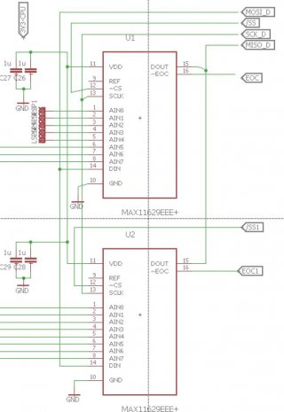
I confirm just with ohm meter that the connections are
like they should be
Here are screen copies of the relevant parts

Screen Shot 2018-04-14 at 15.26.01.jpg
Screen Shot 2018-04-14 at 15.26.59.jpg

I think I got the in/out correct -

I was super excited in the continuity test when I found that two pins where bridged. But that did not change anything.

Hoping this would be something obvious. I put the pin 14 as input and shorted 13/14 together for the SCK - I see the LED light up if I loop fast so the chip is clocked.

- Benni
 
ok - this seems to be some issue with the EOC pin - I probably fixed the SPI issue with the solder bridge - but then the EOC is not going low from the MAX for some reason
if I manually ground the pin I get stuff from the ADC, but not in correct order, i'm going to work on this bit more - feel I'm getting close.

- Benni
 
I have not looked completely through your code, but notice in document:
These devices feature an active-low, end-of-conversion
output.

EOC goes low when the ADC completes the last
requested operation and is waiting for the next input data
byte (for clock modes 00 and 10).

In clock mode 01, EOC goes low after the ADC completes each requested
operation. EOC goes high when CS or CNVST goes low.

EOC is always high in clock mode 11

In your setup code, I think you are in mode 10? If so it says the EOC will go high when you set the CS LOW...

So not sure if your code would work better, maybe something like:
Code:
void readADC()
{
  uint8_t adc_temp;
  int i;
  
  if(digitalRead(EOC) == 0)
  {
    Serial.println("ADC RDY");
    SPI.beginTransaction (SPISettings (4000000, MSBFIRST, SPI_MODE0));
    digitalWrite(SS1, LOW);


      for(i=0; i<MAXCHANNEL_ADCA; i++)
    {
      adc_temp = SPI.transfer(0);
      adc_temp <<= 8;
      adc_temp += SPI.transfer(0);
    }
    Serial.print(adc_temp);
    Serial.print(" ");


    digitalWrite(SS1, HIGH);
    SPI.endTransaction();
  }
 Serial.println();

}

Again just guessing.
 
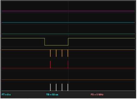
Screen Shot 2018-04-14 at 21.32.48.png

well, I think it's confirmed with logic analyzer that the devices are talking

I put a interrupt on the EOC pin and it triggers.

It seems that I'm not correctly enabling the MAX to continuously make measurements - so when I call the init again and again I get the EOC signal

So I'm going to go over the setup of the MAX chip to see where my error is.

thanks again !
 
Looking at the document: https://datasheets.maximintegrated.com/en/ds/MAX11626-MAX11633.pdf
If you are in Mode: 10 It looks like you need to output a byte to the "Conversion Byte" (Figure 6), to start the transfer...

By the figure you would need to maybe start a transaction Assert CS output a byte (maybe 0), release CS and probably end transaction.
Then wait for the EOC to trigger and do the code you have...

Now depending on how often you want this to work, you might have your current code and feed it the first conversion byte, and when you get the EOC, you read in the results, and then you start the new transaction and output your Conversion byte and return...
 
Ok - got this finally to work.

I was making at least two mistakes

One was I have to CS=LOW, write register, CS=HIGH
I was in some cases writing two registers in sequence a. This seems to be an issue with the MAX chip (or all) - I think you pointed that out in the prev answer ;)

Then it has to be SPI_MODE3 - this got be bit confused.
I get the channels now correct

and then I now use a interrupt to pick up the EOC falling

Thank you for all your help, learned alot.

This is the test code just for reference.
Code:
// 
//  MAX MAX11626–MAX11629/
//  MAX11632/MAX11633
//  Test code
//  -  working somewhat ;)

#include <SPI.h>

#define SS1 10
#define EOC 8

#define MAXCHANNEL_ADCA 8
SPISettings settingsA(1000000, MSBFIRST, SPI_MODE3);


void writeADC(byte b)
{
  SPI.beginTransaction (settingsA);
   digitalWrite(SS1, LOW);
   SPI.transfer(b);
   digitalWrite(SS1, HIGH);
 SPI.endTransaction();
}

void init_adc()
{
   writeADC(0b01101000);  //0x68 // setup reg 
   writeADC(0b00110100);  //0x34  av reg 8 meaurments 

}


void initial_start_ADCs()
{

   writeADC(0b00011000);   // 0x18 reset FIFO 0b00011000
   writeADC(0b10000000 | ((MAXCHANNEL_ADCA-1)<<3));   // 0x80 channels 0b10000000

}


void setup() {
 Serial.begin(9600);
 delay(1000);
 pinMode(SS1,OUTPUT);
 pinMode(EOC,INPUT_PULLUP);
 

  attachInterrupt(digitalPinToInterrupt(EOC), readADC , FALLING);

  digitalWrite(SS1, HIGH);

    SPI.begin();
//    SPI.setSCK(14);
    pinMode(14,INPUT);   // test - Pin13/14 connected together  - as the MAX is connected to 14 - using default CLK

    delay(100);
    init_adc();
    delay(1);
    initial_start_ADCs();
}

void readADC()
{
  unsigned int adc_temp;
  int i;
  

  if(digitalRead(EOC) == LOW)
  {
    Serial.println("ADC RDY");
      for(i=0; i<MAXCHANNEL_ADCA; i++)
    {
      SPI.beginTransaction (settingsA);
      digitalWrite(SS1, LOW);
      adc_temp = SPI.transfer(0);
      digitalWrite(SS1, HIGH);
      
      adc_temp <<= 8;
      digitalWrite(SS1, LOW);
      adc_temp += SPI.transfer(0);
      digitalWrite(SS1, HIGH);
  
      Serial.print(adc_temp);
      Serial.print(" ");

      SPI.endTransaction();
      
    }


 writeADC(0b00011000) ;
 writeADC(0x80 | ((MAXCHANNEL_ADCA-1)<<3));   // 0x80 channels 0b10000000

   
  }
 Serial.println("+");


}

 
void loop() {

 Serial.println(".");
 

 delay(300);
 //init_adc();
}
 
Status
Not open for further replies.
Back
Top