Too much breadboards?

Status
Not open for further replies.

AdmiralCrunch

Well-known member
Hi

I have wired the Teensy 3.6 on a breadboard with some buttons and a 4051.. everything worked fine. Then I attached another breadboard to the cicuit with some 8x 10K potentimenters and another 4051.. now my Teensy is gone away.. no Port.. when I unplug the 5V/GND cables from the third breadboard, the Teensy is there.

Is there something I should know about using too many, or too long cables.. btw making the way, the voltage must go, very big?
 
Not sure what a 4051 is - but feeding it 5V? Is everything touching the [not 5V tolerant] T_3.6 at or under 3.3V?

If the Teensy is leaving it may not have enough supply ?

... what if a second set of PWR and GND wires were run to the rails on the 3rd breadboard? My first connect of power hungry ESP board was not getting enough power on the same small breadboard until I ran the same power with a second wire on the rail closer to the ESP end. ESP would RUN - but not enough power to FLASH when I was trying to update firmware - then I measured the 3.3V at something under 3V when it hit ESP VIN - the second wire made the difference. But that never took the Teensy away.
 
I think I found something

I unplugged everything from the third breadboard and and wired it up again step by step, checking if the Teensy is recognized. When I only have one Potentiometer attached, it works, but as soon as I attach a second potentiometer the Teensy is gone. oO
 
some breadboards are known to have “shorts”, use a different area or change the board altogether
everythings made in china nowadays :D

the wires in jumper cables are hair thin, dont expect it to carry sufficient power to many devices unless you add more cables..
 
some breadboards are known to have “shorts”, use a different area or change the board altogether
everythings made in china nowadays :D

the wires in jumper cables are hair thin, dont expect it to carry sufficient power to many devices unless you add more cables..

Hi,

I tried all you suggested.. different areas and additional wires.. but still the same.. as soon as I attach a further 10K Potentiometer, the problems begin.
But I recognnized something curious..
I unplug the 3rd breadboard and run the Teensy..
then I wire the 3rd Breadboard while the Teensy is running.. everything ok..
then I wire a Potentiometer to this breadboard.. everything still ok ..
then I add a second potentiometer (turned to low, where GND is connected) .. now something curious start to happen with my CD4051 readings (the code is wokring fine I guess, it works perfectly on a other CD4051 whre I have attached 8x switch-buttons).. when I turn the first potentiometer, it is recognized as a value change on the second potentiometer.. oO .. and when I turn the second, nothing happens.. oO .. when I unplug the second potentiomter, everything is fine again .. oO

shoud I somehow debounce or whatever the potentiometers? .. maybe some kind of resistance between poti and GND?
 
Maybe show us photos of how you've actually wired everything.

We're pretty good at noticing problems when you share good photos. For example, on this thread someone was experiencing strange problems with multiple pots through a mux chip. When we got to see the photo, it turned out to be a capacitor that had not been mentioned (before the photo).

https://forum.pjrc.com/threads/3237...cted-to-74HC4051?p=92631&viewfull=1#post92631

We can (probably) help you much better if we can see what you're really doing. It might be something "simple" like that case?
 
hi,

thank you for the suggestions so far.. I have now wired the pots on the breadboard where the teensy is and connected them to the CD4051 where the buttons were before.. but still the same problems.

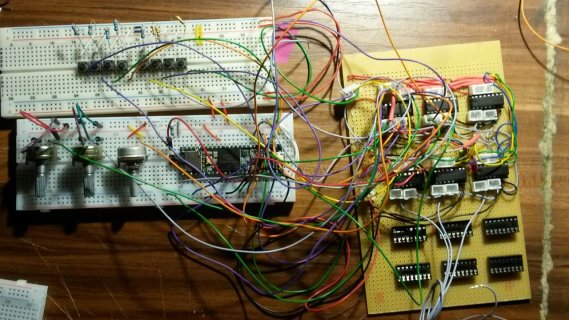
Here is a pic of my setup so far:
20180427_095019.jpg

On the right is my Mux-Board where I will need 12x 4051 to poll all the switches/potis/faders I need.
- The last 6 sockets on the bottom are not connected yet.
- different resitors on the buttons because i had no 10k resitors any more ^^ .. but that works fine

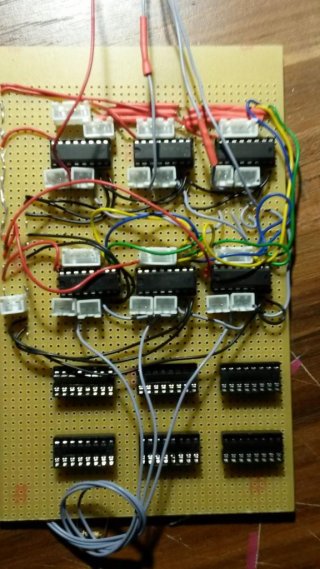
I made a Pic of it 'naked':
20180427_095203.jpg

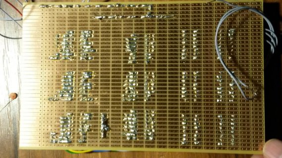
And the backside
20180427_095223.jpg

Edit:
I have now connected just one pot to the IN1 of mux1 (of course all other INs of the first mux to GND) .. it seems to work somehow, but when I turn the pot up to the side where 3.3V is connected, the teensy is not beeing recognized anymore. I then have to turn the pot down to the side where GND is connected and restart the teensy.

basic quastion:
the ICs 1-4 are CD4051BE and then I have CD74HC4051E.. can that be bad? or is that no problem?
 
Last edited:
Maybe your potentiometers are faulty? When teensy is not recognized, check voltage between 5V and GND, is it 5V? same for 3.3V and GND. disconnect power and check resistance between 5V and GND, 3.3V and GND. What is it?
 
wow, 12x4051’s, you coulda just used 3x mcp23s17’s for 48 inputs, and they have poll/ interrupt pin capability

only 4 wires needed to connect to teensy, plus the interrupt pins(if you dont want to poll)
PS, they all share the same chipselect too as theyre addressed independantly, ive got 8 on one chipselect)
 
Maybe your potentiometers are faulty? When teensy is not recognized, check voltage between 5V and GND, is it 5V? same for 3.3V and GND. disconnect power and check resistance between 5V and GND, 3.3V and GND. What is it?

I will check, but I think it's unlikely.. I have tried different potis that all have worked once.. also I tried to connect the pots direct to the teensy... everything fine here.

wow, 12x4051’s, you coulda just used 3x mcp23s17’s for 48 inputs, and they have poll/ interrupt pin capability
yes I know.. I for sure will refactor my project at some stage, but for now I have way too much 4051s :)
 
Status
Not open for further replies.
Back
Top