DigitalWriteFast() to multiple pins simultaneously

Status
Not open for further replies.

jnrohan

New member
I am trying to pulse 8 pins simultaneously and as quickly as possible. I quickly realized DigitalWriteFast() would not be adequate and port manipulation might be the only solution. I found this tutorial very helpful but could not find anything more relevant in the forum.

I was able to write directly to PORTD and get desirable results. However, I noticed that some pins are not getting pulsed, specifically pins 8, 14, 20 and 21.

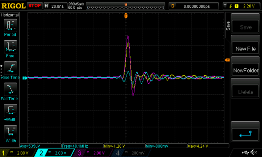
Here's the view on the scope. Showing desirable results (yellow, purple) and no pulse (blue):
NewFile6.png

Here's my code:
Code:
void setup() {
  DDRD = 0xFF;
  GPIOD_PDDR = 0xFF;
}

void loop() {
  GPIOD_PDOR   = 0xFF;
  //delay(1000);    // still no output on some pins
  GPIOD_PDOR   = 0x00;
  //delay(1000);    // still no output on some pins
  //*(volatile uint8_t *)(&GPIOD_PDOR)   = 0xFF; // Tried this instead, didn't work
  //*(volatile uint8_t *)(&GPIOD_PDOR)   = 0x00;
}

I am using a Teensey 3.6. I have verified that all of these pins (2,5,6,7,8,14,20,21) work when I use digitalWrite().

Has anybody with more technical know-how have an idea on how to resolve this?

Greatly Appreciated,
Jacob
 
Have not dug into manual or found my Teensy 3.6 to test with yet, but those port registers are probably 32 bits wide internally - try writing 0xFFFFFFFF

Edit: Found my spare Teensy 3.6 and concur with your results, not all of port D is going active with that code even when using the full register width.
 
Last edited:
Thanks GremlinWrangler! I think that is a great idea. I tried it too, no luck as well unfortunately.
 
This does toggle pin 14
Code:
void setup() {
  DDRD = 0xFFFFFFFF;
  GPIOD_PDDR = 0xFFFFFFFF;
  pinMode(8,OUTPUT);
  pinMode(51,OUTPUT);
    pinMode(14,OUTPUT);
}

void loop() {
  GPIOD_PDOR   = 0xFFFFFFFF;
  //delay(1000);    // still no output on some pins
  GPIOD_PDOR   = 0x00;
  //delay(1000);    // still no output on some pins
  //*(volatile uint8_t *)(&GPIOD_PDOR)   = 0xFF; // Tried this instead, didn't work
  //*(volatile uint8_t *)(&GPIOD_PDOR)   = 0x00;
}

So looks like whatever Macro is being feed with the DDRD/GPIOD lines within the Teensyduino is not fully setting the pin registers, which if I'm reading https://www.pjrc.com/teensy/K66P144M180SF5RMV2.pdf right are all functions of a pin in a register rather than the 8 bit AVR logic of a resgister that configures a function for a port. So doing a pinMode in startup may just automagically do what you need or you may need to dig into the logic behind pinMode and manually set those pin registers yourself. Still something not right here (most likely my understanding) since pin 51 is not toggling with the code above.*

edit: *when I counted pins correctly code above does indeed toggle pin 51 so problem was in measuring the wrong pin.
 
Your code did not work for me, I'm not sure why. Luckily this did work! I am not completely sure what the pinMode() function is doing beyond modifying the data direction register, but I can confirm that all pins are behaving as expected:

Code:
void setup() {
  pinMode( 8,INPUT);  // D3 // Previously, these did not work
  pinMode(14,INPUT);  // D1 // Previously, these did not work
  pinMode(20,INPUT);  // D5 // Previously, these did not work
  pinMode(21,INPUT);  // D6 // Previously, these did not work
  pinMode( 2,INPUT);  // D0 //
  pinMode( 5,INPUT);  // D7 //
  pinMode( 6,INPUT);  // D4 //
  pinMode( 7,INPUT);  // D2 //
  
  pinMode(15,INPUT);  // C0 //
  pinMode(22,INPUT);  // C1 //
  pinMode(23,INPUT);  // C2 //
  pinMode( 9,INPUT);  // C3 //
  pinMode(10,INPUT);  // C4 //
  pinMode(13,INPUT);  // C5 //
  pinMode(11,INPUT);  // C6 //
  pinMode(12,INPUT);  // C7 //
  DDRD = 0xFFFFFFFF;
  GPIOD_PDDR = 0xFFFFFFFF;
  DDRC = 0xFFFFFFFF;
  GPIOC_PDDR = 0xFFFFFFFF;
}

void loop() {
  GPIOD_PDOR   = 0xFFFFFFFF;
  GPIOD_PDOR   = 0x00000000;
  GPIOC_PDOR   = 0xFFFFFFFF;
  GPIOC_PDOR   = 0x00000000;
  //*(volatile uint32_t *)(&GPIOD_PDOR)   = 0xFFFFFFFF; // Tried this instead, didn't work
  //*(volatile uint32_t *)(&GPIOD_PDOR)   = 0x00000000;
  //digitalWriteFast(14,HIGH);
  //digitalWriteFast(14,LOW);
}

And here are the results, showing pin 14 (blue, PORTD) and pin 22 (yellow, PORTC):
NewFile8.png

I was really hoping I'd be able to get this working with 16 pins on the same port, but I noticed there isn't any port with that many pins available according to the Teensey 3.6 schematic. Do you think there could be a work around?

edit: *when I counted pins correctly code above does indeed toggle pin 51 so problem was in measuring the wrong pin.

Haha, I am the master of measuring the wrong pins.
 
Each pin has several registers controlling its function so pretty sure DDRD is an AVR alike macro that turns into multiple commands during compile.

In terms of maximising pin toggle speed you may need to look at the OctWS library and what it does with DMA to clock entire ports of pins with a memory array to make this non blocking, or if you truly need to speed do things the right way and move to an FPGA which is the right hammer for this parallel work.
 
I am not completely sure what the pinMode() function is doing beyond modifying the data direction register

It's writing to the port config register, which assigns the pin to be controlled by the GPIO peripheral. Every pin has an 8-way mux that configures which peripheral actually controls the pin. This is distinctly different from AVR where the GPIO is hard-wired to the pins and overridden by some (but not all) peripherals. On these ARM chips, every pin has a mux which explicitly controls which peripheral has the pin.

All the pins default to "ALT0" which is a low power disabled state, where only the analog functions work. To allow GPIO to have control of the pin, the mux needs to be configured to ALT1.

This stuff is documented in chapter 11 & 12 of the K66 reference manual. Chapter 11 has a giant table starting on page 184 which shows all 8 mux assignments for every pin.
 
Status
Not open for further replies.
Back
Top