Hello,
I have found a teensy 3.2 custom board on github https://github.com/thewknd/teensy-boards/tree/master/Teensy 3.2 reference board clone
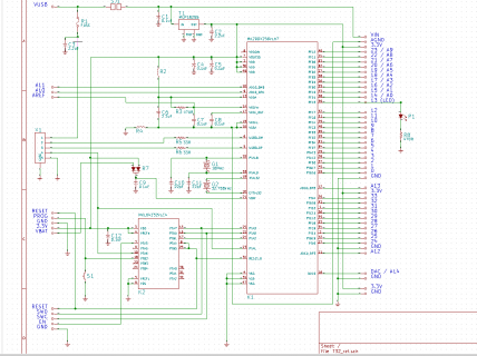
Here is a screenshot(Opened in kicad with https://github.com/sci-bots/teensy-3.2-clone.kicad):

Can i use this schematic as is, and create a circuit out of it ? ( By following the teensy custom board guidance )
Do you have any recommendation or improvements to do ?
Do you think i will encounter any problems if i order the pcb and assemble it ( Considering it is well assembled )
Are the components correct, and can i use generic components for resistance, ferric beads, diodes, and capacitors ?
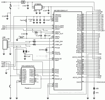
I ask this because i saw that it is a bit different that the original teensy 3.2 one :

I have found a teensy 3.2 custom board on github https://github.com/thewknd/teensy-boards/tree/master/Teensy 3.2 reference board clone
Here is a screenshot(Opened in kicad with https://github.com/sci-bots/teensy-3.2-clone.kicad):

Can i use this schematic as is, and create a circuit out of it ? ( By following the teensy custom board guidance )
Do you have any recommendation or improvements to do ?
Do you think i will encounter any problems if i order the pcb and assemble it ( Considering it is well assembled )
Are the components correct, and can i use generic components for resistance, ferric beads, diodes, and capacitors ?
I ask this because i saw that it is a bit different that the original teensy 3.2 one :

Last edited:

