Strange analogReading struggle with fader

Status
Not open for further replies.

AdmiralCrunch

Well-known member
Hi

I have some of those APLS 10K Dual slide potentiometer, I attached one directly and I read it like

Code:
const int analogInPin = A4;  
int sensorValue = 0;  

void setup() {    
  Serial.begin(38400);
}

void loop() {  
  sensorValue = analogRead(analogInPin);
  Serial.println(sensorValue);
}

.. and it seems to work, but the "resolution" is somehow .. strange .. where 0 should be, there is a 100 (+/- some noise) .. and when I move the slider a little just a little, there is immediately 1023 .. how can this be? has someone experienced something like that ?
 
The lower end pin of the potentiometer is well connected to the AGND pin and the higher end pin to +3.3V? The wiper pin is connected to A4 while you added a 10 nF decoupling capacitor between the wiper and AGND as recommended by the KINETIS ADC application note?
 
For troubleshooting, I recommend connecting a voltmeter. Then you can watch the actual analog voltage at the pin while you move the slider and see the numbers printing. You can also try things like connecting a wire directly to GND or 3.3V (but be careful not to do this when the pot is at the far ends of its range).

Possible guesses: maybe the wire is actually connected to A5 or A3 or some other nearby pin? Or maybe the pot is defective?

Not going all the way to 0 or 1023 is pretty common, especially with linear sliders. A little noise is also common. But you should see pretty good linear change as you move position, not sudden jumps.
 
The lower end pin of the potentiometer is well connected to the AGND pin and the higher end pin to +3.3V? The wiper pin is connected to A4 while you added a 10 nF decoupling capacitor between the wiper and AGND as recommended by the KINETIS ADC application note?

Hi, yes I tried this. (by the way, what is the defference between AND and GND?) I also tried a 100nF capacitor, but still this behaviour.

When I connect the higher-end-pin to 3.3V, the slider sends a value of about 76
..when I now slide it up slowly, it immediately jumps to about 900 and then to 1023

but when I connect the higher-end-pin to Vin, the value jumps to 1023 as soon as I move the slider.


For troubleshooting, I recommend connecting a voltmeter. Then you can watch the actual analog voltage at the pin while you move the slider and see the numbers printing.
I did that.. connected to 3.3V and AGND the slider shows at the lowest point: ~1.2mV
and at the highest point it shows: 2.82V
You can also try things like connecting a wire directly to GND or 3.3V (but be careful not to do this when the pot is at the far ends of its range).
uhm, I did that(?) oO .. but how do you mean "connecting a wire directly to GND or 3.3V" ? Do you mean, that usually I need to put a resistor or something inbetween? oO
Possible guesses: maybe the wire is actually connected to A5 or A3 or some other nearby pin? Or maybe the pot is defective?
yes that was in fact a issue the first time I tried that :D .. but now I triple-check the connections
Not going all the way to 0 or 1023 is pretty common, especially with linear sliders. A little noise is also common. But you should see pretty good linear change as you move position, not sudden jumps.
what sliders do go exact from 0 to 1023? I was told, those 10mm-faders were good(?). I can handle the noise with this ResponsiveAnalogRead(), I think. But I need reliable reading.
 
Last edited:
I am near to surrender with this issue -.-

I have tried all the slide-pots (8 pieces).. the same issue
I have tried it on a ArduiniUno ... same issue
I have tried checked the soldered points and wirering.. same issue

now I have ordered me some new slide-pots to see if it is a hardware-issue.
 
Hi guys,

I have recieved some brand new slide-potentiometers today and just tried them out.. this is definetly not a pot-problem, still the same behaviour.. I tried it on a Teensy 3.2, too :(

what else could cause this problem? has someone a idea?
 
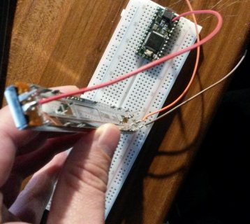
20180523_230755.jpg

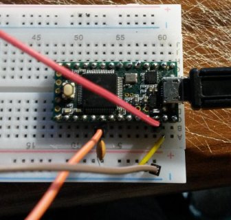
20180523_231217.jpg

what is strange.. the potentiometer only goes to 1023 if connected to Vin..
if conntected to 3.3V it only goes to 845
 
Please use a voltmeter to monitor the actual analog voltage right at the A4 pin.

Pot is connected to 3.3V and AGND:
- pot is closed: 0,2 mV
- pot is in the middle: 28,3 mV
- pot is 3/4 opened: 92,8 mV
- pot is all opened: 2.56 V

Pot is connected to Vin and AGND:
- pot is closed: 0,4 mV
- pot is in the middle: 12.5 mV
- pot is 3/4 opened: 99,2 mV
- pot is all opened: 3,36 V
 
Ah-hahhhh.... Looks like these aren’t linear slider potentiometers but logarithmic (audio taper) pots which aren’t suited for being read with ADCs. To be sure, please disconnect one and measure the resistance between wiper and the bottom pin.
On a linear taper, the resistance would vary roughly between 0R when closed, 5k in the middle, 7k5 at 3/4 and 10k when open. On a logarithmic taper, you’d still have below 1k5 in the middle.
 
Unfortunately yes, at least for a MCU based project. Logarithmic pots are used when it comes to attenuate audio signals in analog circuits, especially mixing desks, etc. Their highly unlinear resistance curve is adapted to the ear’s loudness sensitivity curve which is also highly unlinear (you need 10 times more sound pressure to get the impression of a doubled volume which is pretty exponential). That’s why these potentiometers are called logarithmic (which is mathematically not correct, but it has become a common denomination).
What you will need are linear potentiometers.

thank you so much!! :) .. I was dealing with this for weeks now.. finally I can go now kill myself ;P
 
I use the linear version of these pots on one of my projects and can say they do work. Just happy to see you found the problem.
 
I use the linear version of these pots on one of my projects and can say they do work. Just happy to see you found the problem.

thanks :)

but unfortunately I got the linear version of the same slide-pots now and still, I have the same problem :'(
I really don't know what to do anymore.. tomorrow I will call the shop to unsure they have send me the linear version
 
You can check them by yourself. A pot has 3 pins: Lower end (L), Wiper (W), High end (H).

If checked with a multimeter without being connected to the Teensy, you should see
Wiper at 0%: L to W near 0Ohm, W to H near 10kOhm
Wiper at 25%: L to W near 2.5kOhm, W to H near 7.5kOhm
Wiper at 50%: L to W near 5kOhm, W to H near 5kOhm
Wiper at 75%: L to W near 7.5kOhm, W to H near 2.5kOhm
Wiper at 100%: L to W near 10kOhm, W to H near 0Ohm.
Always 10kOhm between H and L, independent of the wiper position.

If that is the case, next step: Connect L to the Teensy’s GND and H to the Teensy’s 3.3V pin. Do not yet connect the wiper. Now take again the multimeter and check the voltage, not the resistance, this time:
Wiper at 0%: W to L (GND): near 0V
Wiper at 25%: W to L (GND): near 0.8V
Wiper at 50%: W to L (GND): near 1.6V
Wiper at 75%: W to L (GND): near 2.4V
Wiper at 100%: W to L (GND): near 3.2V
If that still woks, you can be sure that the pot is ok.

Now, connect the pot’s wiper to the Teensy’s analog input pin while L remains at GND and H at 3.3V. Without looking at what the running sketch does, check again voltage vs position as just above. If the voltage readings are now different, your sketch does either configure the pin in a wrong way (you shouldn’t use pinMode in your sketch, just leave the pin in its default boot state which is optimal for analogRead) or that analog input is toasted. Try another one.
If the voltage readings remain roughly the same with the connected wiper, odds are good that the sketch will now correctly read the pot position. If not, it’s a software error since you will have proven that the pot is feeding the correct signal into the Teensy.

Oh man, now I’ve rewritten the first 9th grade physics lesson about Ohm’s law and the voltage divider. I hate wasting time on basics and stuff which I consider is common sense. I hope that it helps, at least.
 
Status
Not open for further replies.
Back
Top