MIDI DJ Controller using Teensy 3.6 - am I doing this right?

Status
Not open for further replies.

RedPixel

New member
So I got the crazy idea to create a MIDI DJ Controller using a Teensy 3.6. I'll do a nice write up when I'm finished.

I am comfortable doing some MIDI stuff, writing C code, some soldering and like to tinker. I do not have much microcontroller experience though. I already have the Teensy 3.6, and I have ordered some hardware. I also have written some software and made a little design. Can you guys please check whether I am missing some big things?
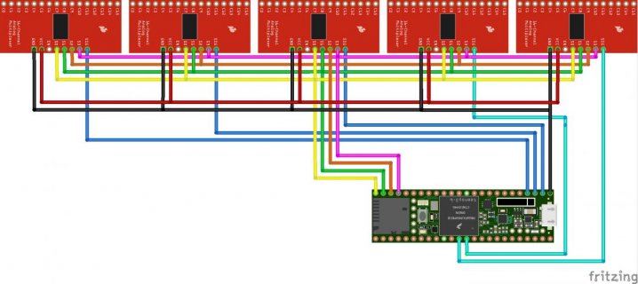
sketch_bb.jpg
For now, this is my design. The three multiplexers on the left will be connected to simple button switches. The two on the right will get all the middle pins from many rotary and slider 10k Ohm potentiometers.

Things I am unsure of:
  • Do I need to connect some/all unused pins to GND?
  • Should I use external power for potentiometers and the Teensy? If so, can I combine that with the usb-power safely?
  • Can I use multiplexers to power LEDs?
  • Am I using correct wire colors?
  • Will multiplexing analog and digital signals like this work?
  • Are there any best practises for MIDI signals/channels/messages?

Here is my code:
Code:
// analog smoothing
#include <ResponsiveAnalogRead.h>
// include the Bounce library for 'de-bouncing' switches -- removing electrical chatter as contacts settle
#include <Bounce.h>
// usbMIDI.h library is added automatically when code is compiled as a MIDI device

// Multiplexer selector pins on teensy
int SELECTOR_PINS[] = {32, 31, 30, 29};

// pins to read
const int AN = 2; // number of analog pins
const int DN = 3; // number of digital pins
const int ANALOG_PINS[AN] = {A0, A1}; // teensy mapping, pin 14,15
const int DIGITAL_PINS[DN] = {0,1,2}; // teensy mapping

const int MAX_PINS = 16; // max number of pins multiplexed per multiplexer
const int ANALOG_MUX_PINS[AN] = {16, 16}; // number of pins on multiplexer used for signals
const int DIGITAL_MUX_PINS[DN] = {16, 16, 16}; // number of pins on multiplexer used for signals

// analog[i][j] corresponds to analog pin i on Teensy, pin j on multiplexer
ResponsiveAnalogRead *analog[AN][MAX_PINS];
byte analog_data[AN][MAX_PINS];
byte analog_data_prev[AN][MAX_PINS];

// digital[i][j] corresponds to digital pin i on Teensy, pin j on multiplexer
Bounce *digital[DN][MAX_PINS];

const int BOUNCE_TIME = 5; // 5 ms is usually sufficient
const int ON_VELOCITY = 127; // pressed button "note" velocity

void setup() {
  Serial.begin(9600);
  setupAnalog();
  setupDigital();
}

void setupAnalog() {
  for (int i = 0; i < AN; i++) {
    for (int j = 0; j < ANALOG_MUX_PINS[i]; j++) {
      analog[i][j] = new ResponsiveAnalogRead(ANALOG_PINS[i], true); // initialize
    }
  }
}

void setupDigital() {
  for (int i = 0; i < DN; i++) {
    for (int j = 0; j < DIGITAL_MUX_PINS[i]; j++) {
      digital[i][j] = new Bounce(DIGITAL_PINS[i], true); // initialize
    }
    pinMode(DIGITAL_PINS[i], INPUT_PULLUP); // internal pullup resistors for digital section
  }
}

void loop() {
  for (int j = 0; j < MAX_PINS; j++) { // loop over multiplexer
    setSelectorPins(j);
    readAnalogs(j);
    readDigitals(j);
  }
  while (usbMIDI.read()) {
    // read & ignore incoming messages
  }
}

void readAnalogs(int j) {
  for (int i = 0; i < AN; i++) { // loop over analog inputs
    if (j < ANALOG_MUX_PINS[i]) { // pin j on multiplexer is actually used
      analog[i][j]->update();
      if (analog[i][j]->hasChanged()) {
        analog_data[i][j] = analog[i][j]->getValue() >> 3;
        if (analog_data[i][j] != analog_data_prev[i][j]) {
          analog_data_prev[i][j] = analog_data[i][j];
          usbMIDI.sendControlChange(16 + j, analog_data[i][j], i + 1);
          // I use CCID 16-31 which are General Purpose Controllers or Undefined:
          // https://www.midi.org/specifications-old/item/table-3-control-change-messages-data-bytes-2
          // the channel is the index of current analog teensy pin index (i)
        }
      }
    }
  }
}

void readDigitals(int j) {
  for (int i = 0; i < DN; i++) { // loop over digital inputs
    if (j < DIGITAL_MUX_PINS[i]) { // pin j on multiplexer is actually used
      digital[i][j]->update();
      if (digital[i][j]->fallingEdge()) {
        usbMIDI.sendNoteOn(j+i*MAX_PINS, ON_VELOCITY, AN + i + 1);
        // note is 16*current digital teensy pin index (i) + current mux pin index (j)
        // velocity is pressing a note (should be 65 to 127)
        // channel is one above the analog + index of current digital teensy pin index (i)
      }

      if (digital[i][j]->risingEdge()) {
        usbMIDI.sendNoteOff(i+j*MAX_PINS, 0, AN + i + 1);
      }
    }
  }
}

void setSelectorPins(int j) {
  byte s0 = (j & B0001) ? HIGH : LOW;
  byte s1 = (j & B0010) ? HIGH : LOW;
  byte s2 = (j & B0100) ? HIGH : LOW;
  byte s3 = (j & B1000) ? HIGH : LOW;
  digitalWrite(SELECTOR_PINS[0], s0);
  digitalWrite(SELECTOR_PINS[1], s1);
  digitalWrite(SELECTOR_PINS[2], s2);
  digitalWrite(SELECTOR_PINS[3], s3);

  // allow 50 us for signals to stablize
  delayMicroseconds(50);
}
 
Wow.... so that's how to initialize bounce and RAR arrays.

Still studying but looks good from what I can see. Did you seriously write this without the hardware already in place?
 
Do I need to connect some/all unused pins to GND?
Just make sure you are not reading any floating pins. Pullups are on the digital lines but you might need to source or sink any unused pins on the analog mux... especially if they are polled in the code. And they need to be stable voltages during testing if you don't have all your pots set up.

Should I use external power for potentiometers and the Teensy? If so, can I combine that with the usb-power safely?
https://www.pjrc.com/teensy/external_power.html ...there is no short answer to power supply.

Will multiplexing analog and digital signals like this work?
yes...although the "like this" part remains to be seen.
 
So I got the crazy idea to create a MIDI DJ Controller using a Teensy 3.6. I'll do a nice write up when I'm finished.

I am comfortable doing some MIDI stuff, writing C code, some soldering and like to tinker. I do not have much microcontroller experience though. I already have the Teensy 3.6, and I have ordered some hardware. I also have written some software and made a little design. Can you guys please check whether I am missing some big things?

View attachment 13913
For now, this is my design. The three multiplexers on the left will be connected to simple button switches. The two on the right will get all the middle pins from many rotary and slider 10k Ohm potentiometers.

Things I am unsure of:
  • Do I need to connect some/all unused pins to GND?
  • Should I use external power for potentiometers and the Teensy? If so, can I combine that with the usb-power safely?
  • Can I use multiplexers to power LEDs?
  • Am I using correct wire colors?
  • Will multiplexing analog and digital signals like this work?
  • Are there any best practises for MIDI signals/channels/messages?

Here is my code:
Code:
// analog smoothing
#include <ResponsiveAnalogRead.h>
// include the Bounce library for 'de-bouncing' switches -- removing electrical chatter as contacts settle
#include <Bounce.h>
// usbMIDI.h library is added automatically when code is compiled as a MIDI device

// Multiplexer selector pins on teensy
int SELECTOR_PINS[] = {32, 31, 30, 29};

// pins to read
const int AN = 2; // number of analog pins
const int DN = 3; // number of digital pins
const int ANALOG_PINS[AN] = {A0, A1}; // teensy mapping, pin 14,15
const int DIGITAL_PINS[DN] = {0,1,2}; // teensy mapping

const int MAX_PINS = 16; // max number of pins multiplexed per multiplexer
const int ANALOG_MUX_PINS[AN] = {16, 16}; // number of pins on multiplexer used for signals
const int DIGITAL_MUX_PINS[DN] = {16, 16, 16}; // number of pins on multiplexer used for signals

// analog[i][j] corresponds to analog pin i on Teensy, pin j on multiplexer
ResponsiveAnalogRead *analog[AN][MAX_PINS];
byte analog_data[AN][MAX_PINS];
byte analog_data_prev[AN][MAX_PINS];

// digital[i][j] corresponds to digital pin i on Teensy, pin j on multiplexer
Bounce *digital[DN][MAX_PINS];

const int BOUNCE_TIME = 5; // 5 ms is usually sufficient
const int ON_VELOCITY = 127; // pressed button "note" velocity

void setup() {
  Serial.begin(9600);
  setupAnalog();
  setupDigital();
}

void setupAnalog() {
  for (int i = 0; i < AN; i++) {
    for (int j = 0; j < ANALOG_MUX_PINS[i]; j++) {
      analog[i][j] = new ResponsiveAnalogRead(ANALOG_PINS[i], true); // initialize
    }
  }
}

void setupDigital() {
  for (int i = 0; i < DN; i++) {
    for (int j = 0; j < DIGITAL_MUX_PINS[i]; j++) {
      digital[i][j] = new Bounce(DIGITAL_PINS[i], true); // initialize
    }
    pinMode(DIGITAL_PINS[i], INPUT_PULLUP); // internal pullup resistors for digital section
  }
}

void loop() {
  for (int j = 0; j < MAX_PINS; j++) { // loop over multiplexer
    setSelectorPins(j);
    readAnalogs(j);
    readDigitals(j);
  }
  while (usbMIDI.read()) {
    // read & ignore incoming messages
  }
}

void readAnalogs(int j) {
  for (int i = 0; i < AN; i++) { // loop over analog inputs
    if (j < ANALOG_MUX_PINS[i]) { // pin j on multiplexer is actually used
      analog[i][j]->update();
      if (analog[i][j]->hasChanged()) {
        analog_data[i][j] = analog[i][j]->getValue() >> 3;
        if (analog_data[i][j] != analog_data_prev[i][j]) {
          analog_data_prev[i][j] = analog_data[i][j];
          usbMIDI.sendControlChange(16 + j, analog_data[i][j], i + 1);
          // I use CCID 16-31 which are General Purpose Controllers or Undefined:
          // https://www.midi.org/specifications-old/item/table-3-control-change-messages-data-bytes-2
          // the channel is the index of current analog teensy pin index (i)
        }
      }
    }
  }
}

void readDigitals(int j) {
  for (int i = 0; i < DN; i++) { // loop over digital inputs
    if (j < DIGITAL_MUX_PINS[i]) { // pin j on multiplexer is actually used
      digital[i][j]->update();
      if (digital[i][j]->fallingEdge()) {
        usbMIDI.sendNoteOn(j+i*MAX_PINS, ON_VELOCITY, AN + i + 1);
        // note is 16*current digital teensy pin index (i) + current mux pin index (j)
        // velocity is pressing a note (should be 65 to 127)
        // channel is one above the analog + index of current digital teensy pin index (i)
      }

      if (digital[i][j]->risingEdge()) {
        usbMIDI.sendNoteOff(i+j*MAX_PINS, 0, AN + i + 1);
      }
    }
  }
}

void setSelectorPins(int j) {
  byte s0 = (j & B0001) ? HIGH : LOW;
  byte s1 = (j & B0010) ? HIGH : LOW;
  byte s2 = (j & B0100) ? HIGH : LOW;
  byte s3 = (j & B1000) ? HIGH : LOW;
  digitalWrite(SELECTOR_PINS[0], s0);
  digitalWrite(SELECTOR_PINS[1], s1);
  digitalWrite(SELECTOR_PINS[2], s2);
  digitalWrite(SELECTOR_PINS[3], s3);

  // allow 50 us for signals to stablize
  delayMicroseconds(50);
}


  • As far as on the Teensy you don’t have to connect the unused pins to ground, for the multiplexers I can’t say otherwise.
  • I don’t believe you should need external power for potentiometers and should be able to power it over usb.
  • You can you use multiplexers to power leds, but you have to make sure your code runs fast enough to have no delays for the leds to look like they are all lit. The leds may also be dim because of how fast they have to switch on and off so you may have to play with resistor/voltage of the leds to get it to look how you want.
  • Wire colors are totally up to you, if you understand it that’s all that really matters.
  • You can mix digital and analog signal as long as you can filter out any interference in code, ResponsiveAnalogRead does a good job of this though.
  • I try to stick to control change messages that are undefined in the midi standard and you’ve already done this. I also don’t use note messages for buttons as most DAWs won’t be able to assign that to a parameter and I wouldn’t recommend to use the internal pull-up resistors in the long run, resistors are cheap and it’s easy enough to put one for each button.

Here’s what the back of a 16 slider and 32 button with led panel looks like using 10 8 channel multiplexers.
View attachment 13836
 
Almost! In fact I was very much able to use and extrapolate this code for my project


This section is almost right:

Code:
void setupDigital() {
  for (int i = 0; i < DN; i++) {
    for (int j = 0; j < DIGITAL_MUX_PINS[i]; j++) {
      digital[i][j] = new Bounce(DIGITAL_PINS[i], true); // initialize
    }
    pinMode(DIGITAL_PINS[i], INPUT_PULLUP); // internal pullup resistors for digital section
  }
}

Should be:
Code:
void setupDigital() {
  for (int i = 0; i < DN; i++) {
    for (int j = 0; j < DIGITAL_MUX_PINS[i]; j++) {
      digital[i][j] = new Bounce(DIGITAL_PINS[i], BOUNCE_TIME); // initialize
    }
    pinMode(DIGITAL_PINS[i], INPUT_PULLUP); // internal pullup resistors for digital section
  }
}

Thanks!!

I ended up using shift registers to control my LEDs: 74hc595 as they hold the last state you put them in.
 
Status
Not open for further replies.
Back
Top