I'm working on a project that requires the microcontroller to communicate with an Engine Control Module over a Serial connection. I had a version of it working with an UNO, but needed the code space of a Teensy to add functionality. My first attempt to running the UNO code had intermittent problems. Data was flowing well and then it didn't. To help with debugging, I decided to use two Teensy's, using one to emulate the ECM. This way I could work and test all on the bench.
This has not worked out. I've worked on it, on and off, for quite a while and just can't seem to find a way to move forward. I realized that in order to test the project device, basically a display unit, with a ECM emulator, that the emulator (and it's software) has to work too. I tried to validate the emulator with my older UNO device, but it was inconsistent, working some of the time and bugging out at others.
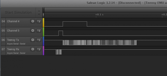
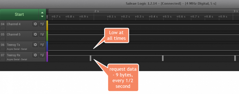
I've hooked up a logic analyzer and it shows that the emulator data stream disappears then that line is connected between devices, but works fine otherwise. This is the problem I'd like to resolve.
At this time I've got a 3.2 emulating the ECM and a 3.5 acting as the display. (I have a couple of LC's, a 3.2 and a 3.6 that could be swapped out if needed).
Here's the emulator code:
And the project display:
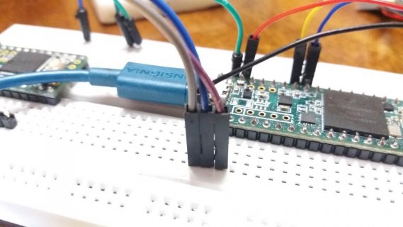
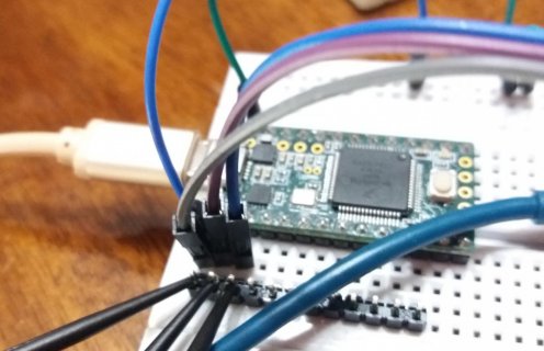
Wiring is Gnd to Gnd, ECM Tx to Disp Rx, ECM Rx to Disp Tx. There is also an OLED display on the 3.5. It uses the I2C port. Right now is isn't doing much, but I'll use it to help debug other stuff if I can ever get past the comms problem.
The logic analyzer shows the results when the ECM Tx is disconnected between to devices. When I connect that channel, the pin status is always low. It does not idle high.
Any suggestions on how to troubleshoot this thing?
This has not worked out. I've worked on it, on and off, for quite a while and just can't seem to find a way to move forward. I realized that in order to test the project device, basically a display unit, with a ECM emulator, that the emulator (and it's software) has to work too. I tried to validate the emulator with my older UNO device, but it was inconsistent, working some of the time and bugging out at others.
I've hooked up a logic analyzer and it shows that the emulator data stream disappears then that line is connected between devices, but works fine otherwise. This is the problem I'd like to resolve.
At this time I've got a 3.2 emulating the ECM and a 3.5 acting as the display. (I have a couple of LC's, a 3.2 and a 3.6 that could be swapped out if needed).
Here's the emulator code:
PHP:
#define teensySerial Serial1 //for ECM comms uses pin 0 for rx and pin 1 for tx
//#define serialTimeOut 5   //timeout for serial communications

byte tps;

const int inPin = 10;
const int sendPin = 13;

byte teensyData[107];  //

//live data to be sent
byte ecmData[107] = {
0x01, 0x42, 0x00, 0x64, 0xff, 0x02, 0x06, 0x7b, 0x08, 0x00,
0x00, 0x00, 0x00, 0x00, 0x00, 0x00, 0x00, 0x58, 0x20, 0x58,
0x20, 0x76, 0x36, 0x76, 0x36, 0x2e, 0x00, 0x0d, 0x9b, 0x04,
0x56, 0x02, 0x7e, 0x02, 0x00, 0x00, 0x89, 0x02, 0x38, 0x06,
0xf2, 0x03, 0x00, 0x00, 0xe8, 0x03, 0xe8, 0x03, 0xe8, 0x03,
0xe8, 0x03, 0x86, 0x04, 0x00, 0x80, 0x00, 0x00, 0x00, 0x00,
0x00, 0x00, 0x00, 0x00, 0x00, 0xf8, 0x00, 0x00, 0x00, 0x00,
0x00, 0x00, 0x00, 0x00, 0x00, 0x00, 0x00, 0x00, 0x00, 0xff,
0xff, 0xff, 0xfe, 0x32, 0x00, 0x04, 0x00, 0x00, 0x00, 0x00,
0x97, 0x00, 0x2e, 0x01, 0xf1, 0xc2, 0x00, 0x00, 0x00, 0x00,
0x00, 0x00, 0x00, 0x00, 0x0f, 0x03, 0x34};


int ByteOffset = 0;
elapsedMillis sinceLastRead;  // for timeout

// ECM communication constants
const byte SOH = 0x01; // Start of Header
const byte PC =  0x00; // PC as target
const byte ECM = 0x42; // ECM as target
const byte SOT = 0x02; // Start of Text
const byte EOH = 0xff; // End of Header
const byte EOT = 0x03; // End of Text (included in length of text)
const byte ACK = 0x06; // Acknowledge code for 'successful' all else means problem

//Set request code to send data from ECM
  const byte ecmReadCmd[9]={
  SOH,
  PC, 	// Sender
  ECM, 	// Receiver
  0x02, // Length
  EOH,
  SOT,
  0x43, // OpCode for send live data
  EOT,
  0xFD};	//checksum: xor checksum bytes 2 thu 8. 0xE8 for "get version" 0xFD for "get run data"  NOTE: the first byte is excluded from the checksum

//----------------------------------------------------------------------------------------------------
void setup(){


  teensySerial.begin(9600);
  delay(1000);
  teensySerial.setTimeout(20);
  //open debug port
  Serial.begin(115200);  // Serial Monitor on PC
  delay(1000);
  Serial.println("Emulation Start");

  pinMode(inPin, OUTPUT);
  digitalWrite(inPin, LOW);

  pinMode(sendPin, OUTPUT);
  digitalWrite(sendPin, LOW);

}
//-------------------------------------------------------------------------------------------------

// Main Processing Loop
void loop(void)
 {

	//ByteOffset = 0;

	if (teensySerial.available())  // there is a byte in the incoming buffer
	{
	digitalWrite(inPin, HIGH);
	teensySerial.readBytes(teensyData,9);
	digitalWrite(inPin, LOW);

		if (teensyData[0] == ecmReadCmd[0] &&   //0x01
		teensyData[1] == ecmReadCmd[1] &&    	//0x00
		teensyData[2] == ecmReadCmd[2] &&    	//0x42
		teensyData[3] == ecmReadCmd[3] &&    	//0x02
		teensyData[4] == ecmReadCmd[4] &&    	//0xff
		teensyData[5] == ecmReadCmd[5] &&    	//0x02
		teensyData[6] == ecmReadCmd[6] &&    	//0x43
		teensyData[7] == ecmReadCmd[7] &&    	//0x03
		teensyData[8] == ecmReadCmd[8])      	//0xfd
		{
			// request ok, send payload
			Serial.println("header good");

			//tps = random (200);
			//secmData[25] = tps;

			digitalWrite(sendPin, HIGH);
			teensySerial.write(ecmData, 107);
			delay(20);
			digitalWrite(sendPin, LOW);

		}

	}

 }
And the project display:
PHP:
#include <Wire.h>  // Include Wire if you're using I2C
#include <SFE_MicroOLED.h>  // Include the SFE_MicroOLED library

#define ecmSerial Serial1 //for ECM comms uses pin 0 for rx and pin 1 for tx

//////////////////////////
// MicroOLED Definition //
//////////////////////////
//The library assumes a reset pin is necessary. The Qwiic OLED has RST hard-wired, so pick an arbitrarty IO pin that is not being used
#define PIN_RESET 9
//The DC_JUMPER is the I2C Address Select jumper. Set to 1 if the jumper is open (Default), or set to 0 if it's closed.
#define DC_JUMPER 1

//////////////////////////////////
// MicroOLED Object Declaration //
//////////////////////////////////
MicroOLED oled(PIN_RESET, DC_JUMPER);    // I2C declaration

const int readPin = 13;

byte ecmData[107]; //live data reported from ECM

// ECM communication constants
const byte SOH = 0x01; // Start of Header
const byte PC =  0x00; // PC as target
const byte ECM = 0x42; // ECM as target
const byte SOT = 0x02; // Start of Text
const byte EOH = 0xff; // End of Header
const byte EOT = 0x03; // End of Text (included in length of text)
const byte ACK = 0x06; // Acknowledge code for 'successful' all else mean problem

//Set request code to read data from ECM
  const byte ecmReadCmd[9]={
  SOH,
  PC, 	// Sender
  ECM, 	// Receiver
  0x02, // Length
  EOH,
  SOT,
  0x43, // OpCode for send live data
  EOT,
  0xFD};	//checksum: xor checksum bytes 2 thu 8. 0xE8 for "get version" 0xFD for "get run data"  NOTE: the first byte is excluded from the checksum

//----------------------------------------------------------------------------------------------------
void setup(){

  ecmSerial.begin(9600);  // baud rate for the ECM is 9600
  delay(1000);
  ecmSerial.setTimeout(20);
  //open debug port
  Serial.begin(115200);  // Serial Monitor on PC
  delay(1000);
  Serial.println("Starting...");

  pinMode(readPin, OUTPUT);
  digitalWrite(readPin, LOW);

  oled.begin();    // Initialize the OLED
  oled.clear(ALL); // Clear the display's internal memory
  oled.display();  // Display what's in the buffer (splashscreen)
  delay(1000);     // Delay 1000 ms
  oled.clear(PAGE); // Clear the buffer.

  oled.setFontType(0);  // Set font to type 0 (5 x 8)
  oled.clear(ALL);     // Clear the page
  oled.setCursor(0,0); // Set cursor to top-left
  oled.println("   Start");
  oled.println("Line 1");
  oled.println("LIne 2");
  oled.println("Line 3");
  oled.display();

}

//Send data request to ECM
void requestData(void) {
  ecmSerial.write(ecmReadCmd,9);
}
//-------------------------------------------------------------------------------------------------

//-------------------------------------------------------------------------------------------------
void readLiveData(void)
	{
	int numBytes = 0;
	byte chksum = 0x00;

	delay (20); // wait for buffer to fill

	if (ecmSerial.available())
		{
		//digitalWrite(readPin, HIGH);
		numBytes = ecmSerial.readBytes(ecmData,107);
		//digitalWrite(readPin, LOW);
		}
		if (numBytes == 107)
			{
			if (ecmData[0] == SOH &&
				ecmData[1] == ECM &&
				ecmData[2] == PC  &&
				ecmData[3] == 100 &&     // total of 107 bytes - 7 which are not counted
				ecmData[4] == EOH &&
				ecmData[5] == SOT)
				{
				if (ecmData[6] == ACK)
					{
						for (int i=1; i<106; i++)  // skip the SOH and the chksum data to calculate the chksum
						{
						chksum = chksum ^ ecmData[i];
						}
					//Serial.println(chksum, HEX);
					if (chksum == ecmData[106]) // if checksum is ok, process data
						{
						Serial.println("ok");
						oled.println("ok");
						oled.display();
						//processLiveData();
						}
						else
						{
						Serial.println("Chksum error");
						}
					}
					else
					{
					Serial.println("Ack error");
					}
				}
		        else
				{
				Serial.println("Header error");
				}
			}
			else
			{
			Serial.print("size = ");
			Serial.println(numBytes);
			Serial.println("Timeout / size error");
			}
	}
//--------------------------------------------------------------------------------------------------

// Main Processing Loop
void loop(void)
 {

	requestData();
	//delay(5);
	readLiveData();

    delay(500);
}  // end of loop
Wiring is Gnd to Gnd, ECM Tx to Disp Rx, ECM Rx to Disp Tx. There is also an OLED display on the 3.5. It uses the I2C port. Right now is isn't doing much, but I'll use it to help debug other stuff if I can ever get past the comms problem.
The logic analyzer shows the results when the ECM Tx is disconnected between to devices. When I connect that channel, the pin status is always low. It does not idle high.
Any suggestions on how to troubleshoot this thing?