Teensy 4.0 (hypothetical) pin assignments

For CAN2, the pins share with Serial1, 2 PWM, and 2 XBAR access pins. This could be abandoned, but then we'd have only 7 serial ports instead of 8. Maybe that's not so bad? But people do use serial ports. Getting all 8 ports (5 on the breadboard pins, 3 on the bottom) seems pretty attractive.
From my perspective this is probably the best choice if you want to include CANFD. As you said earlier it would allow for compatibility with future versions of the T4. Personally, I would prefer to include CANFD. 7 vs 8 Serial ports isn't so bad. Think I've only managed to use 4 or 5 so far. From the manual ref for the 1060 chip that defragster posted it will be able to support both CAN2.0B and CANFD formats.

As an aside I do the new versions of the ST NUCLEO-H743Z will have CANFD available. Found this out before I found the CANFD adapter board that can be used with Teensy's.
 
CAN2.0 is more mainstream in the automotive industry than CANFD, if you were to favour CANFD over CAN pinouts some people might get depressed or not :D

Irregardless, with CANFD being 12MBits and a proper library it can be very beneficial for interconnected nodes :)
 
For me personally I would like to see 8 serial ports as this is the perfect number of ports to make a 1 unit rack box for connecting external MIDI synths to my DAWs. But, as was already stated by some others, I’ve never used CANBus so I can’t really speak for it’s usefullness.
 
Last year the forums had interest in CAN, this year looks pretty dead with an exception of a small handful of people who actually do show interest. with CANFD your not limited to the 8 byte payloads of CAN2.0 but in CANFD you can have up to 64 bytes transfered in a single packet, thats with hardware based CRC and automatic retransmissions that could simplify your projects if you preferred that communication. Just because CAN2.0 limits you to 8 bytes max per payload doesn’t mean you can’t use protocols like ISOTP, CANquitto, UAVCAN, etc to transfer arbitrary amounts of data accross with frame dissasembling at source and reassebling at destination, it sounds complex, but not impossible.

With T3.x I’ve been able to send payloads of 8000 bytes accross CAN reassembled and software CRC verified at other node.
 
I personally have no use for CAN bus applications. my interest is in I2S, SPI, I2C, USB, and serial.
 
For CAN2, the pins share with Serial1, 2 PWM, and 2 XBAR access pins. This could be abandoned, but then we'd have only 7 serial ports instead of 8. Maybe that's not so bad?
Sounds okay for me. Better implement a new function such as CANFD instead of prefering even more serial ports. Not to suppress the serial junkies :rolleyes:
But please keep the second SPI if possible.
 
I personally have no use for CAN bus applications. my interest is in I2S, SPI, I2C, USB, and serial.
Same for me :)

Worse enough that there won't be 4 x 14bit DAC integrated, so SPI will be needed.
On my wishlist, an integrated charge pump would have still been, for bipolar ADC and DAC operation.

Ok, I stop dreaming for now...
 
Last edited:
To put the 'hypothetical questions' back to the fore - losing 1 of the three:
#1:> AD_B1_14 and AD_B1_15, which are present mostly just to give access to a second SPI port and have 2 more analog inputs
#2:> B0_04 & B0_05, which give 2 more PWM, 2 more FlexIO pin (programmable hardware peripherals) and access to a 4th I2C port
#3:> CAN2, the pins share with Serial1, 2 PWM, and 2 XBAR access pins. This could be abandoned, but then we'd have only 7 serial ports instead of 8

The least lossy seems to be #2 if I'm summarizing the posts right? Prior pinout doesn't have to change from the 1050 to get the 1060's RAM, just to add the CANFD port that can xfer up to 8 Mbps (versus 1 Mbps of the other two). Not sure how many generally usable PWM's that leaves, but three i2c's seems to good to keep the needed 1+ open?

… If we were to use the 1060 chip rather than the 1050, should access to some features be sacrificed to gain the 2 signals for the 3rd CAN port (the only one capable of CANFD)?

If so, which 2 pins should get cut out? A couple likely candidates might be AD_B1_14 and AD_B1_15, which are present mostly just to give access to a second SPI port and have 2 more analog inputs, or B0_04 & B0_05, which give 2 more PWM, 2 more FlexIO pin (programmable hardware peripherals) and access to a 4th I2C port.

Or, if we stay with the 1050 chip, would this sort of change make sense anyway for the possible future of stepping up to the larger part?

Oh, if only it were that easy. If we axe CAN1 or CAN2 signals, we also lose other really important must-have features. ...

For CAN2, the pins share with Serial1, 2 PWM, and 2 XBAR access pins. This could be abandoned, but then we'd have only 7 serial ports instead of 8. Maybe that's not so bad? But people do use serial ports. Getting all 8 ports (5 on the breadboard pins, 3 on the bottom) seems pretty attractive.

Unfortunately, the pins where the CANFD signals can be accessed don't have much else going for them. … other shares with part of the 3rd I2S and a couple pins from a GPT timer and a couple XBAR inputs. The XBAR signals are probably the only interesting thing someone not using CAN3 might do with those pins. ...

CAN Question: Can two nearby Teensys use CAN without the transceiver hardware?
 
Not sure how many generally usable PWM's that leaves

Currently 4 of the 24 breadboard friendly pins lack PWM, and so do 3 of the 10 bottom side pins.

2 of the breadboard friendly PWM pins, and 2 of the bottom side ones have a special limitation where they can't produce a 100% duty cycle when configured for full 16 bit resolution. I'm still debating how to handle this, maybe just limit to 15 bits for the normal analogWrite.

All of the PWM pins in this chip have dual-edge placement. On Teensy 3.x, this is only available if you combine two PWM channels together (losing half of them) using the special advanced FTM modes. Dual edge placement means you're not limited to the PWM beginning at the start of the cycle, or center aligning which puts everything into a weird up-down counting mode that makes capture and compare tricky. You can write to registers so the rising and the falling edge happen anywhere you want within the PWM period. ALL the pins from both FlexPWM and the Quadtimers support this! (but those 4 with the full cycle limitation also have some other special limitations with respect to this edge placement if you also configure the period length using certain registers)
 
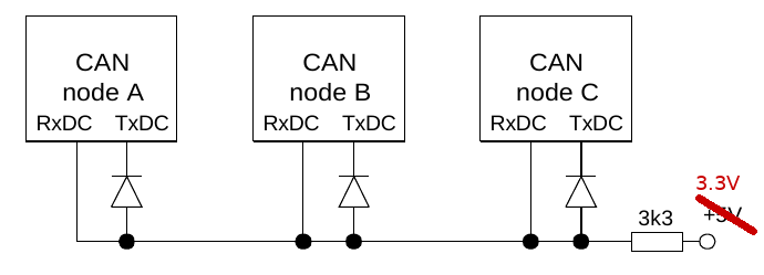
CAN Question: Can two nearby Teensys use CAN without the transceiver hardware?

I believe this would need some off-chip logic, since each chip expects to hear on its RX pins whatever it transmits from its TX pin.

Looks like the logic can be done with diodes and a resistor, according to this app note:

https://www.mikrocontroller.net/attachment/28831/siemens_AP2921.pdf

can.png

To make this work well with 3.3V logic, those diodes might need to be schottky types like BAT54.
 
Looks like the logic can be done with diodes and a resistor, according to this app note:..
Looking at the app note the only limitation of using that approach is the max distance that can be reliably supported. According to the spec all they say is <<1m or <<3 feet or so.

Since my curiosity got the best of me I did a quick google search and found this discussion, CAN possible without external CAN transciever

Just as a side note since tonton81 didn't mention it. His CANquitto library allows for a master-slave relationship with other teensies allowing direct access their SPI, I2C, Analog, Digital pins and of Serial resources.
 
@Paul - As I mentioned in previous posting was I would rather give up 4th I2C versus second SPI...

BUT in all of these trade offs it is hard to give a complete answer without more information. That is how well do the Flex-pins work for functions like SPI?

It has been awhile since I reviewed the documents. But if I remember correctly the SPI on these chips may not have the same functionality as the T3.x where you the queue contains information about state of select pins... So it will be interesting to see to see how we do a library ili9341_t4. And with this see what differences in code we have to do to support regular SPI versus flex SPI...
 
how well do the Flex-pins work for functions like SPI?

I have not yet tried to use flexio, so all I know about it at this point is what I've read. The main info about using it for SPI starts on page 1334.

No FIFO but DMA capable. Lots of flexibility, if you can figure things out from the rather terse info...


But if I remember correctly the SPI on these chips may not have the same functionality as the T3.x where you the queue contains information about state of select pins...

It appears to be built around the assumption of asserting only 1 of the CS pins.
 
@Paul - As I mentioned in previous posting was I would rather give up 4th I2C versus second SPI...
If this is an actual option (but it didn't appear that it was) it might be the better bet (substituting CANFD for SDA4). Only challenge to my soldering skills is whether its on the edge or the underside as I assumed it would be.
 
If this is an actual option (but it didn't appear that it was) it might be the better bet (substituting CANFD for SDA4). Only challenge to my soldering skills is whether its on the edge or the underside as I assumed it would be.

@mjs513 - see this post #158 above with link to Paul's 1st post - I summarized them again as it looked like the one note #3 of horror was primary focus, and this was indeed option #2 in Paul's initial post.

I've never used CAN hardware - would need to buy new cars or setup and local network (post #160?) to use them like CANquitto - but that could be handy for some use cases. I see the transceiver chips (5 Mbps parts) are 50 cents to $1.50. Having this on T_4.0 would allow a server farm to the T_4++. { and a quick read of the MCU manual suggests there is on chip RAM buffer for CAN messages so it would be 'deluxe FIFO' background processing with 'mailbox' control and discard }
 
I have not yet tried to use flexio, so all I know about it at this point is what I've read. The main info about using it for SPI starts on page 1334.

No FIFO but DMA capable. Lots of flexibility, if you can figure things out from the rather terse info...


It appears to be built around the assumption of asserting only 1 of the CS pins.
Which document, is there a link to it up here? I have document I downloaded earlier: KV5XP144M240RM (KV5x Sub-family Reference Manual)

Then for 1060 I see documents like: https://www.nxp.com/docs/en/nxp/data-sheets/IMXRT1060CEC.pdf

or: https://www.nxp.com/docs/en/reference-manual/IMXRT1060RM.pdf

Kurt
 
I think the question is how many users need which feature. I can't estimate that.
Personally I don't need CAN, more than two UARTS or multiple I2C interfaces. 2x SPI would be good, 3x super (although I'm not sure if I'll ever need it).

But what would be really great for me would be 1MB RAM, in whatever configuration.
 
@defragster. With all this discussion on what to sacrifice to get two pins for CANFD, think I lost focus on the actual pin assignments according the spreadsheet in post #20. When you talking about 4th IC I made the inaccurate assumption, probably because I wasn't paying close enough attention, I thought you were referring to:
Code:
20/A10 AD_B0_12   UART1_TX  I2C4_SCL             PWM1_X2                                                           A1:1
21/A11 AD_B0_13   UART1_RX  I2C4_SDA             PWM1_X3                                                           A1:2

Which were not the pins proposed.

Just for reference there are a couple of other advantages to using CAN. The first is that you only need 2 wires (3rd would be common gnd) versus the 6 for SPI, the second is that for SPI you are limited to less than 10 feet (approximate), and think its more susceptible to EMI (this is just a guess based on when we were playing with SPI_MST. With CAN you can get up to 130 feet at max speed. at 50kbs you can theoretically get up to 3280 feet. The main disadvantage is that you need an external transceiver. As you pointed out the are relatively in expensive and to be honest I haven't see a lot of breakout boards for CANFD transceivers.
 
POST #181 - most recent Pin proposal
POST #20 - most recent Pin proposal
I didn't scroll far enough to find that updated post - but just reposted recent notes from Paul where '4th i2c' was noted there in response to another post.

The doc Enhanced Features in i.MX RT1060 Frank_B linked above shows some nice diffs for 1060 "and add some features to improve its performance over i.MX RT1050".

This Pin Count/placement note was promising if it works/routes out
Currently 4 of the 24 breadboard friendly pins lack PWM, and so do 3 of the 10 bottom side pins.
...
 
Last edited:
@defragster. Just wanted to let you where my confusion came from. Just took a look at the ref doc. I think changing from the 1050 to the 1060 would be beneficial whether or not CAN-FD is incorporated into this first version. Think you point out that the price differential is not excessive, just checked Mouser and they are about the same price depending on exact version of the 1050 series. I really am curious on what the final pin mapping will like - I took a wild guess but things my change. Think Michelangelo told the pope when he was painting the cistern chapel that "it will done when its done" - at least in the Charleton Heston movie version (dating my self now).

Oh, btw, I found the 1060 reference manual here in case any one is interested: https://www.mouser.co.uk/pdfdocs/NXP_iMX_RT1060_Reference.pdf.
 
I just noticed the 1060 has a 3rd FlexIO which isn't documented in the 1050 manual. :)

They also brought out much more access to the GPT timer signals. But I'm still leaning towards dedicating one or both GPTs to expand the number of IntervalTimer instances.
 
I just noticed the 1060 has a 3rd FlexIO which isn't documented in the 1050 manual. :)
...

Yes the compare doc Frank posted - the enhanced features doc - noted it could do 2 FelxIO on 1050 and the 1060 can do 3. Reading that shows more diffs than the simple 'table' I linked before. Also ROM grows 32KB. Bummer if adding CANFD loses two available pins for that use.

It even gives a memort map I couldn't find in the Ref Man - four addresses to blocks of 524,287 bytes:
Code:
[B]Table 2. Memory map for on-chip memory[/B]
[U]  Memory Type  |  Start Address  |  End Address  |  Allocation[/U]
  OCRAM           |  2020_0000     |  2027_FFFF  |  OCRAM
  OCRAM           |  2028_0000     |  202F_FFFF  |  FlexRAM (OCRAM)
  DTCM             |  2000_0000     |  2007_FFFF  |  DTCM
  ITCM              |  0000_0000     |  0007_FFFF  |  ITCM

@mjs513 - funny that Ref Man Rev. 0 is the same dated and titled doc linked before (post#146) with same 3,645 pages but 20 MB instead of 30 MB.
 
Back
Top