3.6 board power clarification

Status
Not open for further replies.

rfresh737

Well-known member
Just so im clear about the power going into the 3.5/3.6 boards:

On my bread board, i plug my red wire into the boards 3.3V pin and the other end into my bread boards red line power row? I dont need to plug this red wire into the Vin pin?

Why are there two 3.3V pins? One on each side?

Thank you...
 
Last edited:
It depends on what your external power is:

If your external power is exactly 3.3v, you can plug in the power to one of the 4 3.3v connections (one on each side, one in a through hole in the middle, and one on a solder pad underneath the Teensy). You would plug the ground wire into one of the 6 ground connections (one on each side, one through hole in the middle, one solder pad, and two through holes on the inside that is the USB host on the 3.6 and two additional analog inputs on the 3.5). You do not use the analog ground that is physically between the VIN and main 3.3v pins.

If your power is 3.5-5.5v, you want to plug the power into the VIN pin and not the 3.3v pin.

Alternatively, you could fashion a USB micro-B cable, and use that to power the Teensy.

If you are providing power, you probably want to cut the trace between VIN and VUSB, or you want to unplug the external power when using the USB. This disables the USB plug from providing power to VIN.

As to why there are multiple 3.3v/ground connections, ultimately it was Paul's choice. If you are doing breadboards, having each ground/3.3v on each side, allows you to simplify wiring the wiring to the power rails (i.e. you don't have to have one cable to join the 3.3v and ground between the right and left sides). Similarly for the pads underneath the Teensy, it is useful to have power/ground there, so you can just attach things directly to the pad. For the pins in the middle (reset, program, ground, 3.3v, RTC power), it is useful to have a ground pin there.
 
In addition to what Michael writes:
If you provide, say 5-6V to Vin or 5V USB and therefore use the on-board LDO, you can use the 3.3V pins to power external 3.3V devices (up to a total of 100 mA)
 
I'm powering via a USB cable into the micro b plug. To get power out to one of the power rails on my bread board, which power pin should I connect to on the teensy? The Vin or the 3.3V pin? I'm not using any devices that need 3.3V so I guess I'd plug into the 5V Vin pin?
 
I'm powering via a USB cable into the micro b plug. To get power out to one of the power rails on my bread board, which power pin should I connect to on the teensy? The Vin or the 3.3V pin? I'm not using any devices that need 3.3V so I guess I'd plug into the 5V Vin pin?

Why do you need Power on the Bread board if you are not powering other devices? If you wanted to use voltage to be put back to Teensy, in case of T3.6. it MUST be 3.3V T3.6 is NOT 5V tolerant.
We could be more useful, if you tell us what you wanted to do.
 
>If you wanted to use voltage to be put back to Teensy, in case of T3.6. it MUST be 3.3V T3.6 is NOT 5V tolerant.

That's what I'm confused about. If the 3.6 isn't 5V tolerant, why is there a Vin pin? Isn't that to feed in 5V? All the pins marked 3.3V and the Vin pin, they are all input voltage pins right? So I don't have to use any of them if I'm powering up the 3.6 with my USB plug.

As for the bread board power rail, I need to power up the bread board rail to get power to MCP23017 IO expanders I'm using. The default MCP addressing scheme is such that you need a ground wire to the three addressing pins for the one MCP, but I'm using 4 MCP's, so I need to set some of those addressing pins High. I'm using 0x20 (000), 0x21 (001), 0x22 (010)and 0x23 (011) for the 4 MCP addressing settings. Unless I'm not reading the MCP specs correctly, I need to send power to some of those addressing pins to set them high.

So what's the best way to power up the bread board rail? For the MCP expanders, 5V is fine.
 
Vin is the voltage input which should be no higher than 6V MAX!!!!! Teensy's on-board regulator will handle the conversion from 5V to 3.3V and everything on the T3.6 will be 3.3V only mode. Vin is just a source of power, has nothing to do with functionality of T3.6 other than powering it up......

the MCP expander chips can run at 3.3V too for power, and you'll be able to connect them to teensy fine. BUT, dont power the MCP's with 5V and run the lines to t3.6's I2C lines, you will need a level converter then. The on-board regulator on T3.6 can supply up to 250mA MAX, but don't recommend pushing more than 200 always give a margin, or get a separate powersupply. IF you want you can power the MCP's off the Vin rail of the t3.6 with the 5V input, however, like I said, the I2C will need a voltage level shifter to convert the signals back and forth between 3.3 and 5V between the MCP and T3.6.

Also, for the addressing, the address lines of the MCP can be tied to VCC (MCP power source) or GND directly for addressing
 
>the MCP expander chips can run at 3.3V too for power, and you'll be able to connect them to teensy fine.

OK, I can run the MCP at 3.3V then. On the diagram I have, it shows power into the MCP as the VDD pin 9 with VSS pin 10 being the Ground.

So how best to power the rail with 3.3V so I can wire that into the MCP's?
 
about 2 pins down t3.6’s Vin pin, youll see 3.3v you can use that for the mcp, that way it can be wired safely to teensy as 3.3v chi. use any GND pin. Take care when adding the 4 expanders that they consume less than 200mA by verifying their datasheet
 
Sorry I'm slow to pick this up and still confused. So the 3.3V pin is a power OUT pin? Not to supply 3.3V power IN to the 3.6?

UPDATE: I just read a post by Michael Meissner saying that the 3.3V pin can be used for voltage out to power other devices if I'm powering the 3.6 via the USB cable. So that clears that up.

Thanks everyone for the help!
 
Last edited:
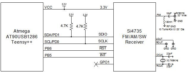
Perfect, don't forget to add pullup resistors for the I2C lines as well, and you should be fine (pull the lines to 3.3V via a 4.7 or 2k resistors (u need 2 resistors))

you can use the illustration of SDA/SCL line of this picture, disregard the other devices

RBDS_SCH.jpg
 
Status
Not open for further replies.
Back
Top