Crosstimer v2

Status
Not open for further replies.

amittel

Member
Hi!
Some remember my old posting about building a 7 segemnt crosstimer.

It's working fine since then, but now I'm thinking of building version 2.
I had some issuses with the first led and the power, which I try to solve in this version.

I don't have a power switch or something else. I always pull the plug.

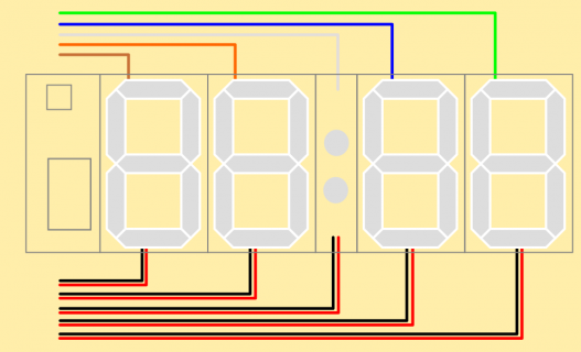
First of all this is the layout of the whole timer
cables complete.png
As you can see I have power at the bottom and data on top. The overall length is about 2m (79in).

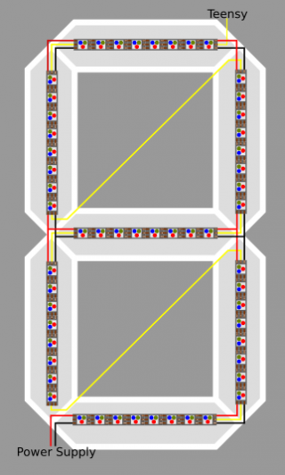
Each 7 segement is wired as followed
cables_leds.png

More photos are in the old thread linked at top.

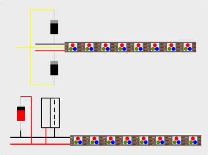
My Ideas for Protection
led_protection.png
  • To protect the LED strip from the data side I would use two Schottkydiodes with a small Uf = 0.1V on every segement
  • On the power side I would put a capacitor (1000uF or more) and a Zenerdiode (5.1V)
  • Also a capacitor on the 74HCT245
More over I'm not using CAT6 cables for data. Should I consider running my data line twisted with a ground line?

Thanks for your help and thoughts!
 
I tried it with the diode array. But had no luck.
I used BAT 86 (Schottkydiode, 50 V, 0,2 A, DO-35).

But I found an article on Adafruit, which states that there should be a data line resistor. So that's what I'm trying now. My diodes are plugable. So more testing :)

View attachment 15745
 
Update on my journey.
I soldered in 470 Ohm resistors. And it doesn't work as expected...

To sum up:
- With diodes in place it worked for two month
- With diodes and data line resistors it work for a month.

The good part is, that the first leds don't get fried anymore. But now other parts of the segment stop working as shown in the attached images.

Let's see, if I can find something to solve this issue. May it be a problem of the brightness?

IMG-20190307-WA0001.jpg
 
I guess, the problem comes from another side. Even if you try to install a maximum of protection, the idea of just plugging and pulling the plug seems bad in conjunction with what I guess are switched mode power supplies. Normally, at this degree of power consumption and the resulting currents, a more sophisticated circuitry is needed to prevent inrush/outrush currents on the primary and the resulting inrush/outrush voltage spikes on the secondary side.

The first suggestion which comes into my mind, is using power supplies which output a separate and delayed "power good" signal after they have stabilized. This could then be used to finally connect the power to the led stripes via relays or MOSFET switches.
 
Thanks for your suggestion.

I did a research and I think I will try the road with the power supply.

This article explains the different circuits used to limit the inrush and for my application it's to complex. Another article also describes some solutions. But still to complex.

So I found the MeanWell UHP-200A. It has a "DC Ok" pin. As shown in the Datasheet it's a switch, which I could hook up to the teensy and then switch the power with a Mosfet (IRFZ34N).

The Article on Adafruit states out, that I should connect first ground, then +5V and then the data lines. Should I go the route? My first idea was just do a high side switching with the mosfet when I get the dc ok signal and leave the rest as is.

I'll work an a shematic to make it more clear and do more reading.

But again, thank you Theremingenieur for pointing me in this direction.
 
Status
Not open for further replies.
Back
Top