Teensy 3.6 multiple I2C devices

Status
Not open for further replies.

scrimarco

New member
Hello everybody,

I am a college student fairly new to arduino/circuits and need some help implementing 2 I2C devices. I'm not too experienced with I2C devices, and am not sure how to run multiple at once (since according to the website: https://www.pjrc.com/teensy/td_libs_Wire.html, there is only one set of I2C pints).

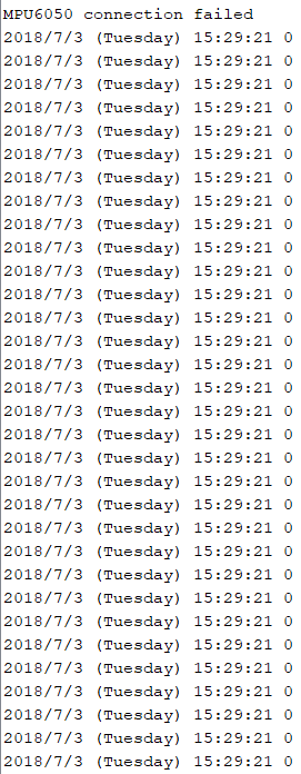
I'm trying to use a MPU6050 accelerometer, and PCF8523 RTC, which both require the SDA and SCL pins.
Can anybody advise me on how I could wire and code to use multiple I2C devices at once?


Thank you!

EDITED: I went more indepth in the comments below, please see those
 

Attachments

  • issues3.png
    issues3.png
    21.4 KB · Views: 291
Last edited:
Here's some more details:

I've notice that both MPU6050 and PCF8523 use the 0x68 addresses, but that the MPU6050 can use the 0x69 address. (I'm attempting to use 0x69)

My wiring is as follows:
-Both devices receive 3.3V from separate outputs
-Both devices go into separate Grounds
-Both devices have SDA connected to the Teensy 3.6 pin 18
-Both devices have SCL connected to the Teensy 3.6 pin 19


Here is my code:
Code:
// Date and time functions using a DS1307 RTC connected via I2C and Wire lib
#include <Wire.h>
#include "RTClib.h"

#if defined(ARDUINO_ARCH_SAMD)
// for Zero, output on USB Serial console, remove line below if using programming port to program the Zero!
   #define Serial SerialUSB
#endif

#include "I2Cdev.h"
#include "MPU6050.h"
MPU6050 accelgyro(0x69);

RTC_PCF8523 rtc;
int16_t ax, ay, az;
int16_t gx, gy, gz;

char daysOfTheWeek[7][12] = {"Sunday", "Monday", "Tuesday", "Wednesday", "Thursday", "Friday", "Saturday"};

void setup () {

#if I2CDEV_IMPLEMENTATION == I2CDEV_ARDUINO_WIRE
        Wire.begin();
    #elif I2CDEV_IMPLEMENTATION == I2CDEV_BUILTIN_FASTWIRE
        Fastwire::setup(400, true);
    #endif
    
  Serial.begin(38400);

  accelgyro.initialize();
  Serial.println(accelgyro.testConnection() ? "MPU6050 connection successful" : "MPU6050 connection failed");

  if (! rtc.begin()) {
    Serial.println("Couldn't find RTC");
    while (1);
  }
    // following line sets the RTC to the date & time this sketch was compiled
    rtc.adjust(DateTime(F(__DATE__), F(__TIME__)));
}

void loop () {
accelgyro.getMotion6(&ax, &ay, &az, &gx, &gy, &gz);
  
    DateTime now = rtc.now();
    
    Serial.print(now.year(), DEC);
    Serial.print('/');
    Serial.print(now.month(), DEC);
    Serial.print('/');
    Serial.print(now.day(), DEC);
    Serial.print(" (");
    Serial.print(daysOfTheWeek[now.dayOfTheWeek()]);
    Serial.print(") ");
    Serial.print(now.hour(), DEC);
    Serial.print(':');
    Serial.print(now.minute(), DEC);
    Serial.print(':');
    Serial.print(now.second(), DEC);
    Serial.print(" "); 
    Serial.println(ax);
    delay(50);
}


Below is an image of my results in the serial monitor.
View attachment 14142
As you can see, the RTC is not recording any time, and the accelerometer fails to startup.


If I disconnect one of the devices, the other one begins working, making me think its an I2C error


My only thoughts is to possibly use another set of SDA+SCL pins or changing the I2c address of the MPU6050, but being the rookie that I am, I'm not sure how to do that.


Thank you for any help!
 
What I would suggest is attach one device and run the example File -> Wire -> Scanner. See what ports are mentioned. If the scanner has errors or hangs, it is a symptom that the device does not have pull-up resistors installed. Similarly, take off the first device, and put on the second device, and see what ports are used. If any of the ports are the same, then you need to change one of the ports (or use separate i2c buses or i2c multiplexers but that is considerably more complex).

If both devices are seen by the scanner, that means they both have pull-up resistors. If neither device is seen, then you need to add pull-up resistors between each of the SDA and SCL pins and 3.3v. Typically on a Teensy, a 2.2K resistor is desired. Devices meant for 5v systems often have 4.7K resistors instead of 2.2K. I don't know if two devices each having 4.7K pull-up resistors would be enough to interfere with each other.

Generally to change the i2c port uses, there is a pin that must be connected to ground or 3.3v to change the port, or there is a solder jumper that must be closed (use solder to connect the two ports) or opened (cut the solder trace so they are no longer connected). You can't just change the code without telling the device to use an alternate port.

One other thought occurs to me is that i2c can run at different speeds. Perhaps the library for the MPU6050 is changing the i2c speed, and the RTC might not be able to run at a faster speed (this is more of an advanced topic).

Please help us and post a link to the precise devices you bought, so we can help you in changing the ports (there are many different products using the MPU6050 and PCF8523 that to give specific advice, we need to know which one you have). It also helps to post a picture of how you wired it up.

Note, the Teensy 3.5/3.6 have a built-in RTC (real-tme clock). You would need to hook up a coin cell battery to it. It doesn't use i2c, but it should be simple to change your sketch. Here is the documentation for the RTC:

See File > Examples > Time > TimeTeensy3 for usage.

If you are using recent Teensydunio IDEs, they will automatically reset the internal RTC each time you reprogram the board. That way the board isn't reset to the compilation time each time you power the Teensy on (providing you have a coin cell powering the RTC).
 
Thank you for the great response! (And sorry for the late response on my side, 4th of July and all...)

Here are the links to the parts I'm using:
RTC: https://www.adafruit.com/product/3295
MPU6050: (I believe its this one) https://www.amazon.com/MPU-6050-MPU6050-Accelerometer-Gyroscope-Converter/dp/B008BOPN40

Running the scanner let me know that each already have pull-ups installed, but as suspected, were running at the same address.

Just as you suggested, it turns out that the MPU6050 has a pin that when set high switches its address to 0x69, allowing both to be used together!


I was actually unaware of the Teensy's built in RTC. I've got some questions, if you know enough to answer them then I would greatly appreciate it!
(1) I have this coin cell battery: https://www.adafruit.com/product/380 How would I connect this to the pins on the Teensy? Obviously I can't just solder to it( heat+battery=:( ), so I'm guessing I would need some external part to house it? If so this might not be the best option, since I need this to fit in a small space if possible (unless of course the housing would be easier to fit into a small space than the PCF8523 chip)...

(2) Would powering the pins stated using a Battery only run the RTC? Or would it power everything else? I'm trying to run only the RTC while the teensy doesn't have power through its main power supply, not everything else.

What I would suggest is attach one device and run the example File -> Wire -> Scanner. See what ports are mentioned. If the scanner has errors or hangs, it is a symptom that the device does not have pull-up resistors installed. Similarly, take off the first device, and put on the second device, and see what ports are used. If any of the ports are the same, then you need to change one of the ports (or use separate i2c buses or i2c multiplexers but that is considerably more complex).

If both devices are seen by the scanner, that means they both have pull-up resistors. If neither device is seen, then you need to add pull-up resistors between each of the SDA and SCL pins and 3.3v. Typically on a Teensy, a 2.2K resistor is desired. Devices meant for 5v systems often have 4.7K resistors instead of 2.2K. I don't know if two devices each having 4.7K pull-up resistors would be enough to interfere with each other.

Generally to change the i2c port uses, there is a pin that must be connected to ground or 3.3v to change the port, or there is a solder jumper that must be closed (use solder to connect the two ports) or opened (cut the solder trace so they are no longer connected). You can't just change the code without telling the device to use an alternate port.

One other thought occurs to me is that i2c can run at different speeds. Perhaps the library for the MPU6050 is changing the i2c speed, and the RTC might not be able to run at a faster speed (this is more of an advanced topic).

Please help us and post a link to the precise devices you bought, so we can help you in changing the ports (there are many different products using the MPU6050 and PCF8523 that to give specific advice, we need to know which one you have). It also helps to post a picture of how you wired it up.

Note, the Teensy 3.5/3.6 have a built-in RTC (real-tme clock). You would need to hook up a coin cell battery to it. It doesn't use i2c, but it should be simple to change your sketch. Here is the documentation for the RTC:

See File > Examples > Time > TimeTeensy3 for usage.

If you are using recent Teensydunio IDEs, they will automatically reset the internal RTC each time you reprogram the board. That way the board isn't reset to the compilation time each time you power the Teensy on (providing you have a coin cell powering the RTC).
 
I was actually unaware of the Teensy's built in RTC. I've got some questions, if you know enough to answer them then I would greatly appreciate it!
(1) I have this coin cell battery: https://www.adafruit.com/product/380 How would I connect this to the pins on the Teensy? Obviously I can't just solder to it( heat+battery=:( ), so I'm guessing I would need some external part to house it? If so this might not be the best option, since I need this to fit in a small space if possible (unless of course the housing would be easier to fit into a small space than the PCF8523 chip)...

Adafruit and others sell a breakout board for the CR1220 and CR2032 batteries (connect a wire between 3v and the VBAT pin and another wire between the two grounds):

While there are rechargeable CR2032 batteries, I have found in practice they go dead in a few weeks or months. The non-rechargeable versions should last for years.

(2) Would powering the pins stated using a Battery only run the RTC? Or would it power everything else? I'm trying to run only the RTC while the teensy doesn't have power through its main power supply, not everything else.
The VBAT/ground pins only power the RTC when there is no power to the rest of the Teensy. If you power the Teensy, it should use the normal power for the RTC. Note, the VBAT pin can only accept 3.3v at max (it prefers 3v I think).
 
Status
Not open for further replies.
Back
Top