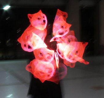
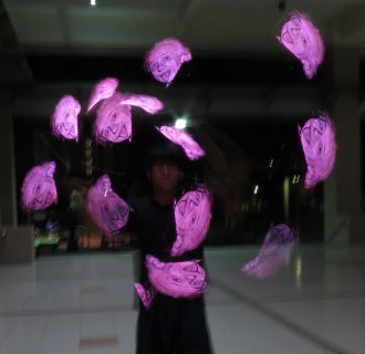
[posted] Venti-POV v2.0 80HD

Po Ting

Well-known member
Venti-POV 2.0 80HD
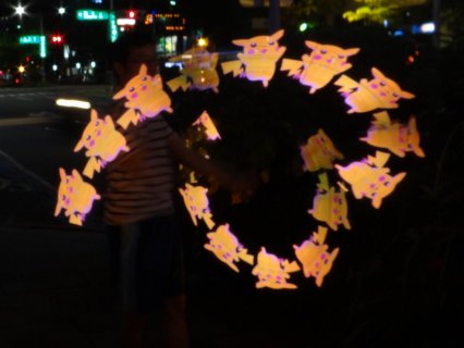
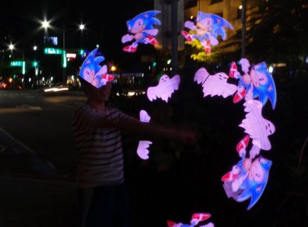
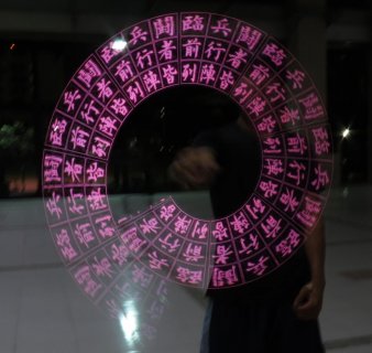
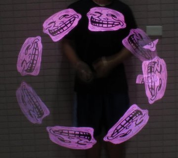
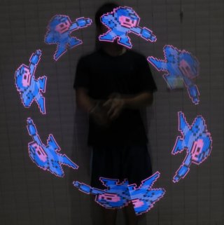
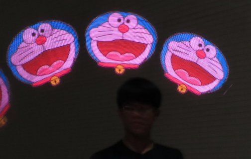
pikaaaa.jpgpikachu sonic.jpgSonic the hedgehog

Introduction: (for short: Persistence Of Vision Poi with Teensy 3.6)
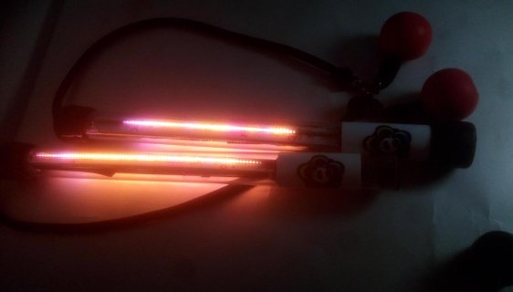
Venti-POV 80HD is a design teensy 3.6, used in flow arts, e.g. Pois, Staves. It is intended to (trying to) sell as a product to local community, but it’s more like a self-using product in the end. “Venti” is my name of it, as I like the word “breeze” in Chinese, so I chose the word in Latin as the name of the POV series. And 2.0 as it’s the second generation of mine. 80HD means 80 pixels in “High Density” of 4 LEDs/cm.
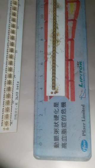
32469097_2006676856018350_6794020250837843968_n.jpgsee the ruler for LED-intensify reference

It is programmed with Arduino 1.83 and Teensy 1.38 , with many library modified for some purpose. The PCBs were designed with Fritzing.

Core function:
It reads the pictures from the built-in SD slot card, and fast enough to perform. First it catches a “settings.txt” file, that user have to define what picture / what time(ms)/what brightness to display at computer, and write in this file. Then T3.6 will display .bmp file in intended timing and order, for performance usage.

It can be controlled through a single touch pad and has many modes, I’m quite proud of this result of coding mysel:cool::cool: .
80HD.jpg
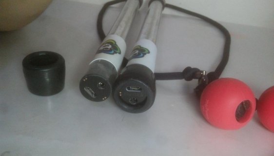
Touch-pad :: T3.6's USB port accessible at the end of the poi, and a DC-plug for battery recharging.
------------------

My features:
->Lithium battery direct powered for T3.6 and apa102.
After on-board regulated, the power for T3.6 sometimes went as low as 2.8V, but still works fine anyway.
->3 parts of PCB : ( the core holder, the touch pad, the LED stick*2)
->the touch-sense pad act as a control button (like a momentary button with no spring -feedback) that debounces, and can tells apart-single click, double-clicks, multi-clicks and long-press.
->Apa102 – 2020 - 80 (24-bit RGB) pixels in 20cm, I had some very hard time soldering with those evil devils.
->Feedback with LEDs – since there are 80 LEDs to use as indicators, it is possible to tell user every detail about the clicking, variable changing, and many details of the device.
->Indicated power level with long-press – almost every LED product on market has this feature.
->Inboard-SD slot with micro-SD : this makes it have ~1,400 rows/second with a 24bit bmp file, also the T3.6 is compiled to 192Mhz for best speed with SDIO, by tests.
->A N-channel Mosfet controls the ground power line for all other devices,so apa102 cannot steal mana from the battery while hibernating.
->Snooze library with SdCard&touch : hibernate with consumption lower than 1mA
->MTP accesses the SD card so don’t need to remove&insert SD card everytime

-----------
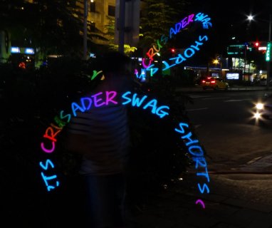
SSC.jpg"SWAG SHORTS CRUSADER" is my friends with same interest in playing flowart performance
Coding of the modes took weeks to complete.
These modes are all reachable by user touch-clicks.
Modes:
1. SD card auto display – For performance, draw pictured(.bmp) from instructions in a defined “.txt” file, it tells the timing/brightness/speed/repeat-time and sequences of picture to display. In this mode single click, DB-clicks cannot interfere your performance and timing, only multi-click and long-press can work.
2. SD card manual mode – draw picture, stick to the same bmp until you clicked. Double clicks change your rune page, to read another .txt file for another pre-defined route.
3. Marque auto – A pre-defined figure with FastLED color palettes to fill in. Auto-switching every 5 seconds.
4. Marquee manual – same above with single click to change palette, DB-click to change figure.
5. Adjustable HSV single color – set Hue/brightness via single/DB-clicks
6. Adjust global brightness – like title.
7. Adjust white balance – switch from pre-defined color temps(from FastLED) or customized settings.
8. Reset all variables
9. Watch Dog Timer reset.
80HD3.jpg
the T3.6 's Mk66 chip is buried in black hot-glue, the SD-slot and program button is visible outside.
It is a hard and sticky kind of glue, and shock-protection is needed for the BGA chip,
not sure how much extra protection is given, but I haven't had a board with black-glue damaged,
In compare I had 2xT3.6s shown poor contact after some shock. I had no skills to repair them so had to replece them.

----------------
I'll talk about schematics and hardwares and other things in replies,
but here ::

Thanks to:
mortonkopf https://forum.pjrc.com/threads/24535-OctoWS2811-POV-reading-BMP-from-SD-card
The project shared was my first of Arduino, it gave me a good first step and confidence on making more complicated POV. Though I still stick to SD and (.bmp) format, I got many other code&hardware improved. All thanks to this starting.

Teensy 3.6 by PJRC – key to high framerate, fast clock, and the onboard - SDIO slot is a powerful feature to do the job.

the FastLED library– const palettes and CRGB struct and many LED-related usage.
http://fastled.io/
Flexitimer2 library – for easy access to timer interrupt used in touch/button action determining.

Teensy Saber from fredrik – I benefit from new version of MTP (using SD.h) from Teensy saber OS, uses SD.h so it can work with snooze Sdcard.
https://fredrik.hubbe.net/lightsaber/teensy_saber.html

Touch.c – touch.c in “\hardware\teensy\avr\cores\teensy3”
(modified so that T3.6 don’t wait for results and pick it up next timer interrupt instead)

Code:
//while (TSI0_GENCS & TSI_GENCS_SCNIP) ; //don’t wait for complete, takes as much as 10ms.
.....
int tsiResult = TSI0_DATA & 0xFFFF; // instead pick it up later. 25ms is enough, 
//warning: this cause hangs if touchread is not called before and TSI0_DATA is probably void or something...
https://github.com/PaulStoffregen/cores/blob/master/teensy3/touch.c

DMASPI library from KurtE - Another key to high-frame-rate, this lets T3.6 to draw the LEDs without waiting, can focus on time-determining step, the SDIO.
https://github.com/kurte/DmaSpi/

Snooze library from duff2013– Provides the device(with SD) hibernate so it is possible to hard-wire power line and can rest long before recharging.
https://github.com/duff2013/Snooze

Adafruit_SleepyDog library – for WTD that resets system hang(unusually) and manual reset option.
Arduino IDE & Teensyduino – Everything worked with them.
Fritzing – Took part in every single PCB I made.
SketchUp – used to draw 3D simulations to make sure PCB and parts fit with my PC-tube.

and thanks to the PJRC Community – had much fun discussing everything and learnt a lot
 
Schematics & code diagram:

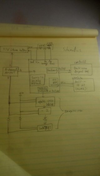
schematics.jpg schematics like mentioned at features above, see the hand-writing.

Specific pins used in features:
Battery power measuring : A4(set as gnd), A5(analog Reader) : using internal reference, and with a 2.2K&10K to divide voltage level.
N-channel MOSFET gate: pin 14(A0)
DMASPI to apa102 chains: pin 11&13 (Dout and Clock of hardware SPI)
Touch-sense: pin 23(A9)
-----------
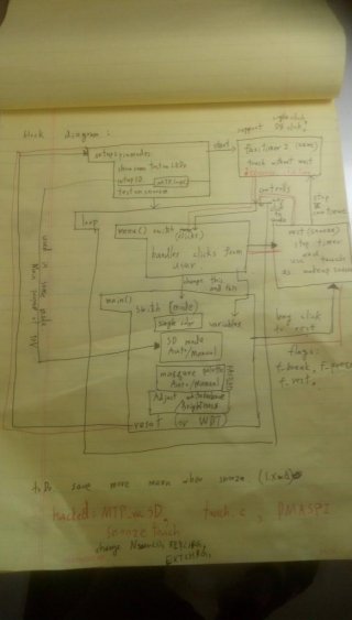
diagram.jpg Diagrams of code
-----
Setup:
pinMode // set them to what they had to.
setupthings // such as SD,Flexitimer2 so clicks start working
showsomeLEDtest // so that’s easy to sure hardware is fine
testonsnooze // to check with hibernate.
MTP.loop() // if USB connection is present, loop this loop
breaks with DB-click Or just skip if not,
------------
loop:{
Menu(): { this is the most important handler to let user able to switch between modes, and change variables via DB-clicks/multi-clicks.

Mainswitchcase() { do the modes-function like mentioned above.

Rest() { stops the flexitimer2, pull-down the N-MOSFET gate, SPI port and anything the drains mana, and hibernate with snooze, wake with A single touch and resume power supply and flexitimer2.
-------------
Flexitimer ISR: {
Every 25ms this is called to check if the touch-pad(or button) was clicked, deal with the results and launch the next touchread(but don’t wait ).
Sets break flags if situation met.

-------------
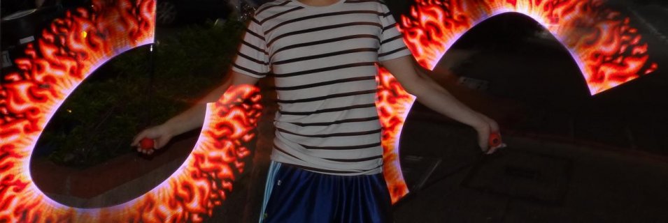
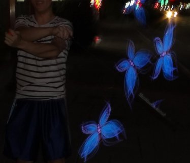
fire.jpgsome kind of fire fly.jpg butterfly
 
Hardwares

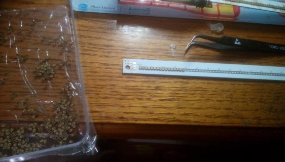
apa102-2020.jpg1. prepare LEDs
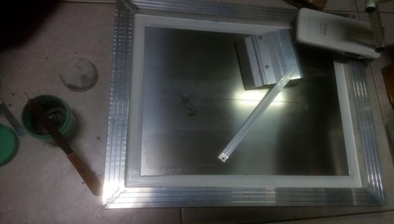
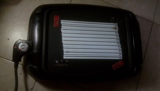
stencil.jpg2. Stencil and apply solder paste
paste&place.jpg3. put those tiny LEDs with tweezers
cook .jpg4. cook them!
5. clean up excess solder and all short/bridges

Due to the expensive of materials, and personal project was such small amount not appropriate for automatic-smt.
one of the major challenge of this project falls on apa102-2020 hand-soldered with stencil /paste,
needs hot-air and iron repair afterwards, so many shorts a board of 80 Leds took ~2 hours, however they did work after cleaning,
that gives hope to my long torture of cleaning up.:p

80HD2.jpg
------------
Hardwares:

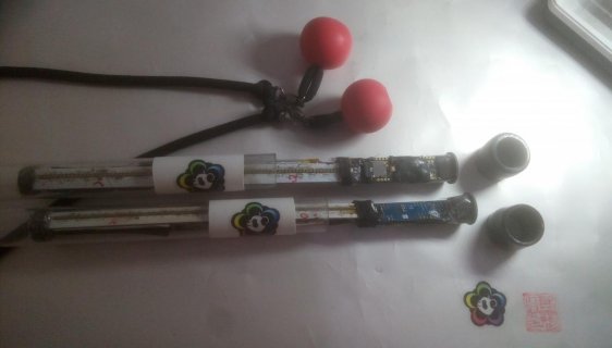
Poly Carbonate tube: (ID*OD: 22*25mm)overall length of this poi tube is 32cm.
the tube gives enough protecting , usually your PCB/wires will fail much more often than the tube.

Power: two small package lithium batteries, with 450mAh each, makes 900mAh at total.

PCB core is parted into 3,
The LED board – holds the apa102-2020 in place, the other side of board have pads for battery connection.
The core board – holds the teensy 3.6, voltage divider resistors, N-channel MOSFET, DC-plug for charging and connector to the three PCBs.
The touch-Pad – used for touching, also slighty bigger then PC-tube so it stucks the device in the same place, I don’t need to drill holes and hold it on the tube. See picture for referece. The core is interchangeable with any empty tube, such as a staff-tube.

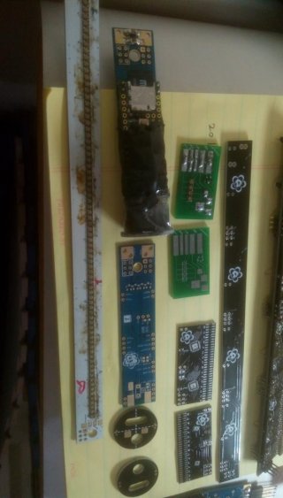
boards2.jpg the boards at left were used in 80HD,
the blue one is the core board; the long white one is the LED board; and the circle black one is the touch-Pad

---------
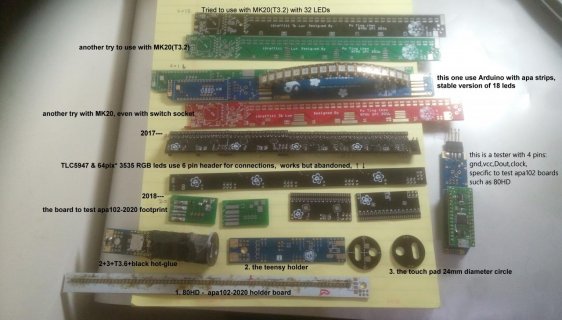
some struggling histories:

2015
JUL - start study about Arduino
SEP - first POV made-with Nano&SD&ws2812 air-wired
OCT- heard of teensy and PJRC
DEC- tried a PCB with MK20, but failed with bad solder and design.
2016
APR- switched to apa102
2017
APR- a first working POV with 72 LEDs&SDIO&teensy 3.6 with air-wired board (https://forum.pjrc.com/threads/3002...Build-Tutorial?p=138973&viewfull=1#post138973) it has a huge area and good POV, but long staff build(160cm) makes it bad to play with.
JUL- drawn a board with 3535LED &TLC5947 as driver, worked but abandoned for complication. (https://www.facebook.com/PandaSpectrum/videos/1805451026435406/?t=10 )
JUL- Tested prototype pcb footprint of apa102 and worked (https://forum.pjrc.com/threads/3002...Build-Tutorial?p=155355&viewfull=1#post155355
2018
MAY- PCB hardware of 80HD assembled, and planned features worked. (https://forum.pjrc.com/threads/3002...Build-Tutorial?p=178970&viewfull=1#post178970)
JUN- Coding complete, and a nice/stable working prototype poi for picturing is done. Thus I have those tooked pictures.


boards22.jpg a good half of the boards were failed/abandoned
SO GOOD THAT ELSE WORKED!
 
Some more photos

tree under sky.jpg"tree by dawn" some picture actually need to be adjusted on PC, for gamma correction
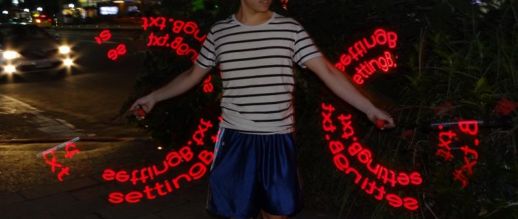
settingb.jpg a "bmp" with "settingB.txt" to show the "page" you're in
runez.jpg colorful runes
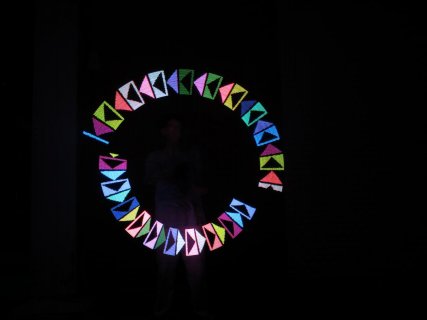
IMG_3179.jpg IMG_3184.jpg
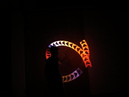
this two are marquee mode, with arrow/triangle figures, they are not the 80HD POV but 36HD POV instead,
however the marquee display functions are mostly the same
and I forgot to took photo with marquee mode with 80HD :(


I don't know anything about MCU/Arduino/8051/whatever electronics, before 2015 June.
It's more than two years after I first mess with home-made POV devices, I still remember stuffs seldom work properly when I was still new.
Never thought of making a stable 80 HD POV and have good-enough effects, since 80HD is about the POV with most pixels you can find in market @2014-2015
(and now they got 200 and 256 pixels lol, :p )

Keep moving on and anything could be possible!
Hope my experience can encourage anyone in the community to keep pushing on their projects :) :) :)

TODO in future:
->More pixels (e.t.c 200HD), will need more speed on reading data.
->Find SPI-flash or other storage devices much faster, or cooler.
->DO some remote control/ synchronizer.
->Make different POV hardware version with 5050 package. As I see big POV companies most have 80HD in a “Lite” version of 4pixel/cm and a “Classic” version of 2pixel/cm
And the bigger area did different objective.
 
Some extras

Here are some more about how I setup the details of a perform-project.
project.jpg
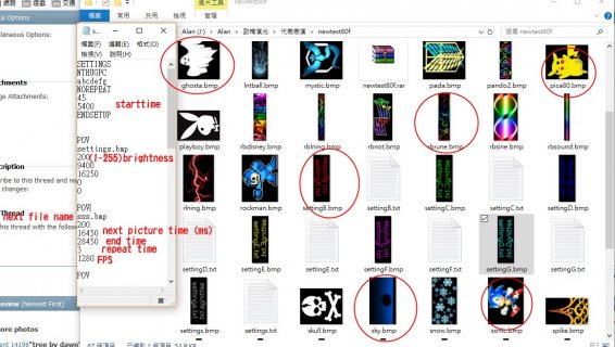
the red circles are pictures that tooked photo at comments above,
mostly with ~1/4 shuttle, aperture of 8.0 , and a flash on to capture the player.
Left is one of the "settings.txt", the text filename and all variable of it is defined by my code. It is the core file in SD.
if any of the settings (frame-speed, repeat times) is 0, then it is unlimited.

speed.jpg
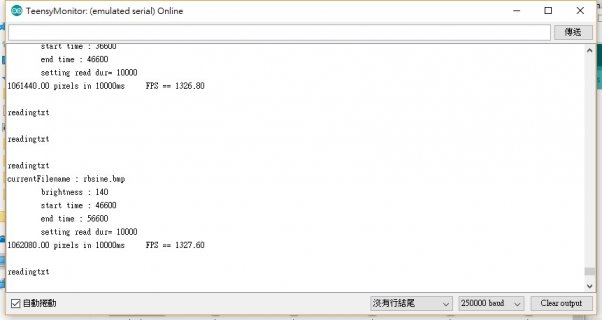
use the serial monitor for debug and see the exact frame speed (or row speed)

the fastest here by far is ~1425 FPS, @192Mhz , FPS of other clock settings are:
~1327 @240Mhz, ~1194@216Mhz, ~1325 @ 80Mhz, ~1236 @168Mhz, ~1420 @144Mhz,
~1320 @120Mhz, ~1416 @96Mhz, ~1281 @72, ~1397 @ 48Mhz, ~1280@24Mhz

I don't have a clear idea about why, but if 50Mhz > (Mhz/2^n) > 40Mhz than its probably fast, this case 192Mhz/4 yield a 48Mhz.
Should have something to do with SDIO clocks. I'm suprised by the speed@24Mhz, clearly the storage-device is most speed-determining.

at 192Mhz , different cards may have different speed, ranged from 1100 to ~1450 FPS.
above 1000 is pretty enough, but pictures may need adjust on PC for better POV effect.

Xcel.jpg
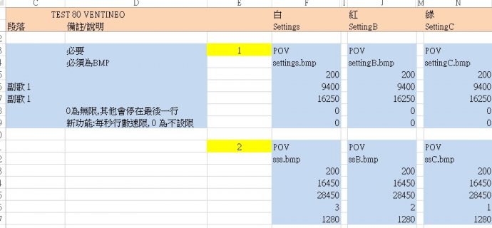
Absolute timing(to ms) was used to follow a music, I use Audacity to get the absolute timing of a music,
And excel for easier manage to multi-pages, comments and cleaner views.


If you wish to see the project files used in a PC, here's a zip of the example project, with 7 pages and 7 pictures used per page,
note that there is no limit to picture per page, but there are only 7 pages as I coded to. :)
https://drive.google.com/open?id=19-waVrGo7ohmufluRxPrfQ8ore51o00W
 
What a mistake.

Just out of curiosity about how fast is pure-SPI can do,
and found that with SPI but not DMASPI it has ~1520FPS @192Mhz
turns out that I forgot to set the clock of my DMASPI so it's using default settings:(:(:

with correct settings it uses 16Mhz for DMASPI , ~1830FPS @240Mhz,180Mhz---96Mhz, ~1700@72Mhz,
(16Mhz has a approx. 6000FPS maximum from my calculation of 32bit/per pixel *80leds)
later I test different microSDs,
and the difference between cards became much bigger(1200~2800FPS)
1200FPS from a 128MB card, 1800 from 256MB card, and 2600 from SANDISK 8/16GB (class4), 2700 from 32GD SANDISK (class4)
(the 128/256 card's from alibaba and speed varies each card)
way more than enough.
with this speed maybe 160HD or 200HD is reachable with good POV effect.
MUST TRY THIS SOMEDAY
----------------------------
And here's more photos

IMG_0021.jpgIMG_0024.jpgIMG_0031.jpg
IMG_0023.jpgIMG_0007.jpgIMG_0013.jpg
 
Last edited:
AWESOME WORK!!

Question: I just tried compiling your POV sketch on Github. No dice. Now, I realize that its name includes the word "corrupted" in it. Is it supposed to be functional?

Figured I'd report in, on the chance it's supposed to work :)
 
AWESOME WORK!!

Question: I just tried compiling your POV sketch on Github. No dice. Now, I realize that its name includes the word "corrupted" in it. Is it supposed to be functional?

Figured I'd report in, on the chance it's supposed to work :)

I just compiled it with my Arduino 1.85 newest build and its compile-able .

It is a less_featured version back in 2016_MARCH. Calling it "corrupted" might be wrong as its only less_featured with a low bmp count limit and strict file names.
notice my comments in the start of program "Arduino328_APA102_SD/ornot POV stick" , its coded and used on Arduino Nano.
to use in one of the PCB mentioned above: "stable version of 18 leds"
see album for its marquee effects, not very good design then. "https://www.facebook.com/pg/nthugpc/photos/?tab=album&album_id=593865460789012" 2016/MAR/20

it was far more improved 2 years later, 18 leds were made of NANO and were enough for some of pictures,
see : "https://www.facebook.com/PandaSpectrum/photos/a.1593897504257427.1073741835.1488312524815926/1971267109853796/?type=3&theater" 2018/MAR
but by far I've done, 36 leds is the limit on atmega328p, for usable POV flowart device.

The corrupted version needs very lots of change to achieve greater NUM_LEDS and file reading, adapt it to teensy 3.6.

if you were planning to make a POV with 72 leds or something, this version can be a stepping stone to understand all things related,
with Teensy 3.6 you don't even need DMASPI and still can get a good POV_FPS with 80 leds

also, if you were new to solder, I STRONGLY ADVICE YOU ENHANCE YOUR SOLDER SKILLS AND START ON STRIP/5050, before you work on apa102-2020.
 
@embedded-creations

thanks for the link! It's useful for anyone would make their own POV

I use my own board for many reasons,
preferred density/count and size,
there is also special designed route so the resistance by trace is same to each LED,
stripped-LED can easily see decay of brightness over length.
also because I can source the LED chip here in my country, since it's made here.
Further prototype/production will be easy for me.
 
Po Ting where can we find your full code at? If it's on github, can you please provide a link? I desperately want my poi working from an SD card more than anything.
 
Po Ting where can we find your full code at? If it's on github, can you please provide a link? I desperately want my poi working from an SD card more than anything.

Hi Frank,
you can find an older version for arduino nano here :
https://github.com/Alan-NTHU/POV-Venti---flow-art

currently I'm not planning on publishing Teensy version of code yet, however you can find many other code here:
https://forum.pjrc.com/threads/30020-Teensy-APA102-POV-Poi-Pixel-Poi-Build-Tutorial
or other source from instructables.com
https://www.instructables.com/id/Arduino-Pixel-Stick/
I haven't look for new reference for a while, like 3 years, cause I already built what I met and too busy for improvements :p
there should be plenty of new codes somewhere
hope you can build one too
 
currently I'm not planning on publishing Teensy version of code yet, however you can find many other code here:

you published the most difficult to obtain: "the idea"
If you made it happen, someone else can do it.
so why not get full credit?
 
you published the most difficult to obtain: "the idea"
If you made it happen, someone else can do it.
so why not get full credit?

hi alezarate,

Sure, I shall publish my work in a while.

You are correct,
I'm just not yet convinced if I can't find any commercial value with my design
It didn't gave me much over two years :) just very fun flowing with it and showing to my friend
I'm currently switching my job from flow art maker to something else,
for the best value of my work it should just be open sourced
Though I'm not the first or last of this kinda POV project.

and to be honest it probably never going to be a match to those commercial ones (Light toy, Ignis, etc)
As without molding (of silicon shell) and professional PCB design or years of durable testing, and a good UI interface, it just can't
I have to repair it a few times though I didn't use it often

I'll need some time to organize(if I would) and publish it up in catalogs
should include : Arduino full folder(since I use a version and many self-modified library 2 years ago, still not updated)
fritzing PCB designs, exported gerber, Arduino script for teensy,
please follow this post, it should be here

Warnings: it will be very messy in script, and everything else, behold.
I doubt if people can be patient enough to read my messed materials :p

Thanks for pushing me,

Regards,
Po Ting
 
First my codes,
should need to use some my specific libraries,
(though if I remember correctly, the same library with 1.8.7 compiles too)
this was the full folder of my used version and libraries,


and this was the .rar of my code when the post was published.

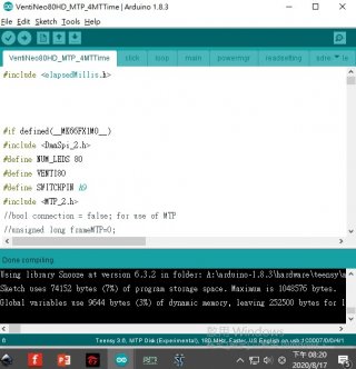
it should work(compile) with teensy 3.6, 180Mhz and with MTP selected
see the screenshot, tested, still can successfully compile

work.jpg
 
Back
Top