what could cause this behaviour with 4051-muxes?

Status
Not open for further replies.

AdmiralCrunch

Well-known member
I have a ton of pots and buttons connected to 14x 74HC4051's.. I often have to unplug everything, measure, solder, and re-wire the whole thing..
sometimes it happens, that a mux that is used for potentiometers only outputs me 0 ot 1 .. (?)

.. i dont't know what it is, I restart the whole thing a thousand times and somehow the mux finally outputs correct analog values..

where can this come from?
 
Hard to say with no actual hardware (or schematic) in front of me. If all the "ducks" need to be aligned precisely before it works I would expect a timing issue somewhere, or faulty code. Decoupling capacitors required? Better power supply regulation required? Not accurately following the datasheet for design implementation? Too high impedances in your circuits? ...

For troubleshooting can you get, say, 5 pots working correctly all the time? If so, try adding a few at a time until it goes berserked again and then analyse it?

I've started a project with 19 potentiometers (-waiting for pot delivery-) with no muxes. Will see what that mess will create.
 
I have disconnected (isolated) everything for testing and every component (row of pots, row of buttons, a single mux, etc) works fine... now I have the situation that this behaviour is gone and everything wirks as it should.. but I know, that next time I will re-wire the project I will have to deal with it again.
 
Designing a huge circuit board for all your components (pots, buttons, mux ICs) and adding a socket for the Teensy should solve all your wiring issues.
 
Loose wires? Or wires accidentally touching each other?

yes that was my first idea, too .. I already made Dupont-Plugs / jacks everywhere.. but somehow it occurs sometimes.

Designing a huge circuit board for all your components (pots, buttons, mux ICs) and adding a socket for the Teensy should solve all your wiring issues.

I already targeted this and am exercizing designing one with KiCad.. but I would like to have a full functioning prototype first.
 
Another (but less likely) possibility is too little delay between changing the mux channels and actually reading the signals.

Unlike a real mechanical switch with metal-on-metal contacts, those mux switches are basically resistors when they're on. The actual value of their resistance can vary, depending on which chip you used and what voltage it gets on its supply pin. Some chips are under 10 ohms, but many others can be near 1K if they're designed to 5 to 10 volts but you run them on only 3.3V.

If you have substantial capacitance on the switched side of the mux, it takes a brief time for the voltage to settle. Teensy runs very fast, so if you change the mux and then try to read the voltage without any delay, your code might be reading the signal while the voltage is still changing.

If you have a huge mess of wires, maybe that capacitance varies depending on how you most & position stuff? But intermittently connecting wiring is probably the more likely explanation.

Great explanation, thanks :)

I try to clean up the wire-mess as far as it is possible. What connectors would you suggest, for using when it comes to connecting frontpanel-controls (pots, sliders, etc) to a PCB ? Molex? Dupont?
 
What connectors would you suggest, for using when it comes to connecting frontpanel-controls (pots, sliders, etc) to a PCB ? Molex? Dupont?

Depends whether you're willing to buy an expensive crimp tool. ;)

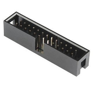
But for large numbers of wires, shrouded dual-row headers, IDC sockets and ribbon cable are hard to beat. Pressing the IDC connectors together can be a challenge. If you're on a budget, often you can get free 34 & 40 pin cables from ancient PC (used for floppy drives and pre-SATA hard drives)... if you know anyone with a box of old cables or any place that recycles PCs. If you're going to be plugging and unplugging the cables, get the headers with the plastic shroud. It keeps the pins from bending if you don't pull the cable off straight, and if the socket as the polarity notch it forces correct orientation, and the shroud prevents off-by-one mistakes when plugging the cable in.

header.jpg
 
Depends whether you're willing to buy an expensive crimp tool. ;)

But for large numbers of wires, shrouded dual-row headers, IDC sockets and ribbon cable are hard to beat. Pressing the IDC connectors together can be a challenge. If you're on a budget, often you can get free 34 & 40 pin cables from ancient PC (used for floppy drives and pre-SATA hard drives)... if you know anyone with a box of old cables or any place that recycles PCs. If you're going to be plugging and unplugging the cables, get the headers with the plastic shroud. It keeps the pins from bending if you don't pull the cable off straight, and if the socket as the polarity notch it forces correct orientation, and the shroud prevents off-by-one mistakes when plugging the cable in.

View attachment 14237

great, thanks :))
 
Status
Not open for further replies.
Back
Top