Hello all,
Awhile back I started work on a project to make a homemade internet-connected barbecue thermometer to address the shortcomings of commercially available units.
I prototyped the device on an Arduino Uno + Raspberry Pi B+, and am now working on building a unit based on a Teensy LC and an ESP8266 (ESP-WROOM-02) module, with the goal of having the unit last 24 hours on 2xAA batteries.
This is the first time I have laid out a board, and while I did a lot of research, I would appreciate anybody who could take the time to offer feedback and suggestions for improvement.
A couple of notes:
Thanks for your feedback!
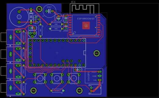
Top:

Bottom:

Schematic:

Awhile back I started work on a project to make a homemade internet-connected barbecue thermometer to address the shortcomings of commercially available units.
I prototyped the device on an Arduino Uno + Raspberry Pi B+, and am now working on building a unit based on a Teensy LC and an ESP8266 (ESP-WROOM-02) module, with the goal of having the unit last 24 hours on 2xAA batteries.
This is the first time I have laid out a board, and while I did a lot of research, I would appreciate anybody who could take the time to offer feedback and suggestions for improvement.
A couple of notes:
- I placed the Teensy where I did to accommodate the placement of other items on the board while still allowing accessibility to the USB port for code updates. Obviously it made trace routing a bit hairy but I think it worked out.
- I'm intentionally trying to stick with PTH components (the castellated ESP module being the notable exception) because my soldering skill is still pretty novice-level and my equipment is abysmal.
- I did read several places about having separate ground planes for analog and digital; however, the Teensy LC does not appear to have a distinct AGND port like the other 32-bit Teensy's, is this worth the effort? Also, the signals I'm sampling are low (read: no) frequency.
Thanks for your feedback!
Top:
Bottom:
Schematic: