Audio-MIDI-PCB for Teensy-3.6/3.6

Status
Not open for further replies.

C0d3man

Well-known member
Hi all,

I am working on a synth emulation of the DX7 FM synthesis (see MicroDexed). It is based on the famous engine of the open VST/AU/LV2 Dexed plugin. Currently it works really stable and sounds good (video and sound demos next weeks...).

Currently I am using a self-made stripe board with the MIDI circuit from the Teensy web page and the Teensy audio board. I want try to make a (universal) PCB for Teensy-based synths and saw that there is a simple and cheap audio output solution using the PT8211. I started to learn KICAD and made my first circuit plan: View attachment TeensyMIDIAudio.pdf.

What do you think?
- may this work?
- are there other users interested in this project?

Regards, Holger
 
Glad you got it working.

On the schematic, you might check R2, R2 & C5. The capacitors are meant to be connected directly to the PT8211 chip. The 10 ohm resistor is meant to provide some small noise isolation between the "digital" 3.3V power and the PT8211 power. Looks like this might be arranged "backwards" on the schematic. The PT8211 will probably work this way, but the noise performance will not be as good.
 
Hi all,

I learned much about and with KICAD and added some more options to my board. Everything is located at https://about.teahub.io/dcoredump/TeensyMIDIAudio.

Because this is my first "big" PCB project it would be nice if some of the professionals can take a look at the circuit - hopefully not telling me that I made hundrets of mistakes. I tried to create a "modular" PCB which should enable different assembly-options for different use-cases. I am not sure if combining a socket for the Teensy-Audio-Board AND a DIP socket for the PT8211 AND a solder option for the PT8211 SO-package is a good idea. But if this would work, it would be a nice option to assemble one of the different options for audio I/O.

Here is a part of my README which describes the project:

Code:
## Description

This PCB is a summary of several circuits for the Teensy. It adds the following features to one board:

    MIDI I/O with DIN connectors
    Audio I/O with the Teensy-Audio-Board
    alternative solution: Audio output with the PT8211
    headers for analog and digital I/O (for all pins which are not used for the above features), e.g. for connecting rotary encoders, potentiometers, switches, …
    headers for 3.3V, 5V and GND
    connector and header for USB host (only Teensy-3.6, e.g. using as MIDI port)
    connectors for audio output (and input when using Teensy-Audio-Board)
    USB-B connector for supplying power
    I2C header with pullup resistors (which can be disabled)

You need not equip all parts if you don’t want to use all the features.

## Idea behind

This is my first creation of a complex board and my first time using KICAD (http://kicad-pcb.org/). I created this PCB for having a flexible microcontroller-synth-plattform. The first implementation for this is a port of the DX-7 emulation of Dexed called MicroDexed (https://about.teahub.io/dcoredump/MicroDexed). First I used a stripe board as a prototype and stackable connectors for the Teensy-3.6 and the Teensy-Audio-Board. After trying around I found out that a simple LCD display and an encoder would be helful to change banks and sounds. So I decided to create a better plattform for this and created a flexible PCB.

The same PCB should make availabe a cheap and simple or more complex contruction on top of the same hardware base. So you have the option to simply use the PT8211 (with only audio outputs) and the onboard USB-MIDI as base for a synth or a full armed version with DIN-MIDI, encoders, LCD display and Audio input and output.

You can build MIDI playable synths, effects or just sound generators - it’s your part to decide what to do. For this the Teensy is really a very good platform. You can use the Arduino-IDE and several very good libraries especially for the audio stacks. Also there are many third party libraries for nearly every hardware which exists - or you can decide to write your own library.
Sources used

    Teensy-Audio-Board: https://www.pjrc.com/store/teensy3_audio.html
    PT8211 circuit: https://www.pjrc.com/store/pt8211_kit.html
    Teensy MIDI circuit: https://www.pjrc.com/teensy/td_libs_MIDI.html
    Creating sound/effect stacks: https://www.pjrc.com/teensy/gui/

## Thanks

A big thanks for all who made Teensy and the software around working. Especially the guys from the forum, which are very helpful and have patience with persons who start with hardware and microcontroller business.

Also a big thanks for the KICAD guys - this software is really awesome.

And not to forget the Arduino guys - IMHO they are some of the founders of the idea of making “things” with microcontrollrs easier.

And, of course all Open-Source developers who let us take part of their work by opening their code as free software.

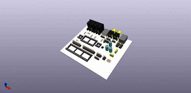
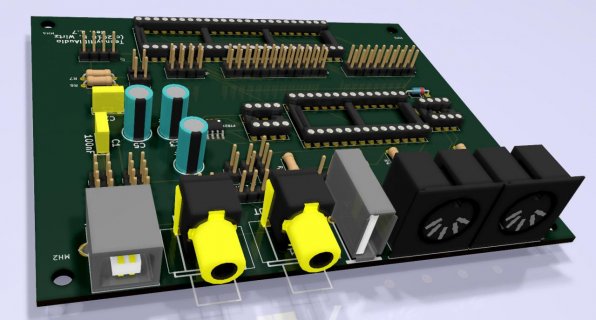
TeensyMIDIAudio-3d.jpg (This picture shows not the stereo link RCA connectors. I am planing to add vertical stacked stereo RCAs)

Ahh - forgot to add the schematic: View attachment TeensyMIDIAudio.pdf

Thanks a lot for reading!

Regards, Holger
 
Last edited:
I think I am nearly ready before creating a small badge of PCBs as a prototype. Will report here of my journey.
TeensyMIDIAudio-3d.jpg
 
Last edited:
If you're routing the USB host data lines across that board, might check that you've kept them together and their lengths are approximately equal. If that's a 2 layer board (or 4 layers without a solid ground plane), it's also important to route a GND trace together with the D+ & D- signals.

The USB host port runs at 480 Mbit/sec. PCB routing can matter for signals of such high bandwidth.

Thanks Paul! I am using the USB-B connector only for powering and the USV-A connector (vertical) only with short data lines towards a pin-row behind (for connecting via parallel flex cables towards the USB-host on top of the T_3.6). I will try to adapt the layout for the USB-A connector according to your information.

Regards, Holger
 
Status
Not open for further replies.
Back
Top