Issues with connecting ILI9341 TFT Touchscreen to Teensy 3.6

Status
Not open for further replies.
Hello all, I'm using a Teensy 3.6 and I recently picked up a 240x320 SPI TFT LCD Touchscreen with a ILI9341 Controller chip (exact product: https://www.amazon.com/HiLetgo-240X320-Resolution-Display-ILI9341/dp/B073R7BH1B ). I've been trying to get it to work but everything I try doesn't seem to work. No matter what I do, all I get is a white screen. I've checked every source I can find on the internet and this forum and nothing seems to work. I don't know if the screen is broken or if I'm just bad at hooking it up. I'm not going to post the source code because I've just used the ILI9341_t3 examples built into Teensyduino. Additionally I've used the same hookups that the page on PJRC instructs: https://www.pjrc.com/store/display_ili9341_touch.html . I really don't know what's going wrong and it's quite frustrating, any help is appreciated!
 
*bump* because I've tried many times again and still no luck, I suppose I should add in that I'm using the teensy audio shield but I don't think that's the problem.
 
I had a bad white screen issue - noted around in a couple posts. In my case it seemed solder closing J1 [ IIRC ] on back bypassed a component that was to make it 5V tolerant and now 3.3V only.

If using audio shield the SPI pins are different - no code listed showing that was accounted for.

Also no way to tell if you got the same device as they seem to be a bulk china production item that may not always be the same. Buying from PJRC gets a tested one at about the same price and the chance to buy a new Teensy.
 
Hard to know without actually seeing the hookup and or knowing what you have tried. It looks very similar to the one by PJRC. You say that you are trying the examples from ili9341_t3 library (graphictest?)

Again hard to know what is going on, without actually seeing it. Example We may find out that you are using a breadboard and did not solder in the pins (seen this several times). Or maybe missing a wire or...
 
I've just used the ILI9341_t3 examples built into Teensyduino. Additionally I've used the same hookups that the page on PJRC instructs: https://www.pjrc.com/store/display_ili9341_touch.html
.....
I suppose I should add in that I'm using the teensy audio shield but I don't think that's the problem.

There are 2 connections documented, standard and the alternate for the audio board. Hopefully you used the audio board connections?

The examples in ILI9341_t3 have the standard connection, so at the very least you have to modify the example for those other pin numbers.

Usually these things don't work due to mistakes or misunderstanding in wiring or how to edit the code. If you look over the many threads on this forum, you'll see we're very good at figuring these things out when you show us good photos of how you actually connected everything, and how you actually edited the code. Without that, we still try to guess, but blind guessing isn't very effective.
 
Hard to know without actually seeing the hookup and or knowing what you have tried. It looks very similar to the one by PJRC. You say that you are trying the examples from ili9341_t3 library (graphictest?)

Again hard to know what is going on, without actually seeing it. Example We may find out that you are using a breadboard and did not solder in the pins (seen this several times). Or maybe missing a wire or...

I had a bad white screen issue - noted around in a couple posts. In my case it seemed solder closing J1 [ IIRC ] on back bypassed a component that was to make it 5V tolerant and now 3.3V only.

It came with headers pre-soldered so I've been using my breadboard to test it. I'm at work right now so I can't send a photo but it should be all the right hooks ups as documented on the PJRC tutorial. I'll try to send a photo tonight

There are 2 connections documented, standard and the alternate for the audio board. Hopefully you used the audio board connections?

...

Usually these things don't work due to mistakes or misunderstanding in wiring or how to edit the code. If you look over the many threads on this forum, you'll see we're very good at figuring these things out when you show us good photos of how you actually connected everything, and how you actually edited the code. Without that, we still try to guess, but blind guessing isn't very effective.

I was using the audio board connections, I'll send some photos and the code I used when I get home from work.
 
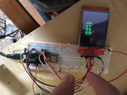
Well, upon reattaching the wires, it seems to work?? I'm just as confused as you are. However the touchscreen does not seem to work. Attached is the current set up, and the code I used, perhaps y'all have some advice.

image_40037873.jpg

Code:
#include <ILI9341_t3.h>
#include <font_Arial.h> // from ILI9341_t3
#include <XPT2046_Touchscreen.h>
#include <SPI.h>

#define CS_PIN  8
#define TIRQ_PIN  2
// MOSI=11, MISO=12, SCK=13

XPT2046_Touchscreen ts(CS_PIN, TIRQ_PIN);

//XPT2046_Touchscreen ts(CS_PIN);  // Param 2 - NULL - No interrupts
//XPT2046_Touchscreen ts(CS_PIN, 255);  // Param 2 - 255 - No interrupts
//XPT2046_Touchscreen ts(CS_PIN, TIRQ_PIN);  // Param 2 - Touch IRQ Pin - interrupt enabled polling

// For optimized ILI9341_t3 library
#define TFT_DC      20
#define TFT_CS      21
#define TFT_RST    255  // 255 = unused, connect to 3.3V
#define TFT_MOSI     7
#define TFT_SCLK    14
#define TFT_MISO    12
ILI9341_t3 tft = ILI9341_t3(TFT_CS, TFT_DC, TFT_RST, TFT_MOSI, TFT_SCLK, TFT_MISO);

void setup() {
  Serial.begin(38400);
  tft.begin();
  tft.setRotation(1);
  tft.fillScreen(ILI9341_BLACK);
  ts.begin();
  ts.setRotation(1);
  while (!Serial && (millis() <= 1000));
}

boolean wastouched = true;

void loop() {
  boolean istouched = ts.touched();
  if (istouched) {
    TS_Point p = ts.getPoint();
    if (!wastouched) {
      tft.fillScreen(ILI9341_BLACK);
      tft.setTextColor(ILI9341_YELLOW);
      tft.setFont(Arial_60);
      tft.setCursor(60, 80);
      tft.print("Touch");
    }
    tft.fillRect(100, 150, 140, 60, ILI9341_BLACK);
    tft.setTextColor(ILI9341_GREEN);
    tft.setFont(Arial_24);
    tft.setCursor(100, 150);
    tft.print("X = ");
    tft.print(p.x);
    tft.setCursor(100, 180);
    tft.print("Y = ");
    tft.print(p.y);
    Serial.print(", x = ");
    Serial.print(p.x);
    Serial.print(", y = ");
    Serial.println(p.y);
  } else {
    if (wastouched) {
      tft.fillScreen(ILI9341_BLACK);
      tft.setTextColor(ILI9341_RED);
      tft.setFont(Arial_48);
      tft.setCursor(120, 50);
      tft.print("No");
      tft.setCursor(80, 120);
      tft.print("Touch");
    }
    Serial.println("no touch");
  }
  wastouched = istouched;
  delay(100);
}
 
Not easy to be positive with same color wires going off the photo top. I see pin 2 to touch IRQ in black I think which is good. It may have a different touch controller if all properly wired. Is that 5V going somewhere? It should run from 3.3V.
 
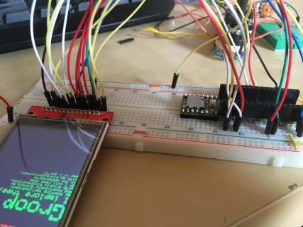
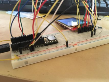
I spent a little time looking at the new photos. There a lot of wires with the same color that go up over the top of the photo. Each of the touch screen wires seems to have a same-color wire coming down to the Teensy side to the right pin, so I'm guessing it's probably wired up correctly.

Maybe one of those breadboard wires is defective? I've personally hit this problem before, actually a couple times. They're cheaply made and use incredibly thin wire. A broken wire might also explain why it didn't work the first time but magically came to life when complete re-wired... maybe the bad wire got reused on the touch side rather than the display pins?

I personally use #22 solid wire for all my breadboarding work, since those cheap wires also tend to be little resistors and can't conduct even 100 mA without significant voltage loss!

If not the wires, then maybe this display simply has a defective touchscreen or controller chip? When we test the displays here (the ones PJRC ships actually are fully tested by real humans in the USA) about 1 out of every 200 fails with a non-responsive touchscreen.
 
I now realize how bad the photos are lol but I think I understand what could be the issues, these jumpers aren't the greatest. Thank you so much for looking into this and helping me out!
 
I now realize how bad the photos are lol but I think I understand what could be the issues, these jumpers aren't the greatest. Thank you so much for looking into this and helping me out!

The pictures are good enough to see the “cold solder” joints on the teensy 3.6 header pins.
I would reflow the soldered pins on the teensy PCB.
First use braided solder wick with flux to remove excess solder, DO NOT over heat the PCB.
 
Last edited:
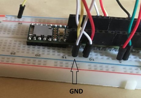
The pictures are not the best, the way I see it you have 3 white wires and one of them is connected to GND is that correct?pic2tft teensy.jpg
 
Like others I am having difficulty figuring out which pins connect to where?

The main thing I am wondering is the connection for MISO. I believe from the last program I have seen on this thread that
#define TFT_MISO 12

But in the pictures I dont think I see anything hooked up to pin 12? Not sure where you have MISO connected to?
 
Status
Not open for further replies.
Back
Top