ThatSwedishGuy
Member
Hi!
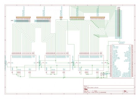
I'm currently in the process of adding some new MIDI-capable thumb pistons to my digital pipe organ, and I plan on using the Teensy 3.2 as it's perfect for this. The plan is to use a couple of MCP23017 IO expanders to handle the 19 pushbuttons and their built-in LED's. As not all LED's will be used, it would technically be possible without expanders, but I want to future-proof for when (not if ) I decide to add more buttons.
The thing is that I'm not sure about if the built in pull-up resistors of the MCP23017 (100k) will be enough. It will at 3.3V give me 33 µA of current though my switches and I'm not sure that is enough to overcome the (unspecified) wetting current of the switches. I have no idea what current would be sufficient to keep oxidation down, especially at 3.3v. Maybe 1 mA with 3.3K resistors would be better? Am I overthinking this? I'd rather do it right the first time so I don't have to take the organ apart more times than necessary.
The buttons I plan on using are the Adafruit 16mm Illuminated momentary pushbuttons https://www.adafruit.com/product/1479. I would prefer real organ thumb pistons, but they are very expensive (I've seen prices around 20-50 USD a piece engraved).
Any input on this would be greatly appreciated.
Edit:
I'm thinking maybe active high would be a better solution, but then the question is what pull-down resistor values that are appropriate. If I were to aim for 10 mA though the switches I would need a 330 Ohm resistor for pull-down, but would that be enough to keep the input low when the switch is open? Or maybe 5 mA would be enough.
I'm currently in the process of adding some new MIDI-capable thumb pistons to my digital pipe organ, and I plan on using the Teensy 3.2 as it's perfect for this. The plan is to use a couple of MCP23017 IO expanders to handle the 19 pushbuttons and their built-in LED's. As not all LED's will be used, it would technically be possible without expanders, but I want to future-proof for when (not if
The thing is that I'm not sure about if the built in pull-up resistors of the MCP23017 (100k) will be enough. It will at 3.3V give me 33 µA of current though my switches and I'm not sure that is enough to overcome the (unspecified) wetting current of the switches. I have no idea what current would be sufficient to keep oxidation down, especially at 3.3v. Maybe 1 mA with 3.3K resistors would be better? Am I overthinking this? I'd rather do it right the first time so I don't have to take the organ apart more times than necessary.
The buttons I plan on using are the Adafruit 16mm Illuminated momentary pushbuttons https://www.adafruit.com/product/1479. I would prefer real organ thumb pistons, but they are very expensive (I've seen prices around 20-50 USD a piece engraved).
Any input on this would be greatly appreciated.
Edit:
I'm thinking maybe active high would be a better solution, but then the question is what pull-down resistor values that are appropriate. If I were to aim for 10 mA though the switches I would need a 330 Ohm resistor for pull-down, but would that be enough to keep the input low when the switch is open? Or maybe 5 mA would be enough.
Last edited:


