Switching SPI modes

Status
Not open for further replies.
Hello,

I am having trouble communicating with two chips on the same SPI bus (one mode 1 and one mode 3). I have tried a number of things and I am all out of ideas, so any help would be greatly appreciated! I would rather not separate them onto separate busses, but I might have to at this rate.

If the two chips are connected, I can talk to either one fine, as long as I don't try and talk to the other. If I try and communicate with both, I lose the ability to communicate with either.

If I remove either chip physically, I have the same problem. If I try and talk to the now removed chip, I lose the ability to talk to the existing chip.

If I make the "SPISettings" the same for both chips, I can still talk to one of them.

Weirdly, if I change the SPI_modes to 0 and 2, my code works fine (I have double checked the data-sheets and the modes should definitely be 1 and 3).

I think the problem is swapping over between the two SPISettings, but I am not sure how I can address this. I have a logic analyser in the post!

Thanks in advance,

James
 
Thanks, I will give that a go. Is it good practice to add a tri-state buffer for each chip?

I have tried the test with the 10K resistors, and MISO line is not being pulled up or down by the chips. It floats around the centre. For one chip the communication is disrupted by the measurement -- I am not sure if this is significant. I will try implementing the buffer anyway.

I get the same problems when one chip is disconnected from the circuit, which is what I find confusing. It is almost like the SPISettings are not changing cleanly from one to another.

Any more ideas are welcome!

James
 
Last edited:
Thanks, I will give that a go. Is it good practice to add a tri-state buffer for each chip?

I have tried the test with the 10K resistors, and MISO line is not being pulled up or down by the chips. It floats around the centre. For one chip the communication is disrupted by the measurement -- I am not sure if this is significant. I will try implementing the buffer anyway.

I get the same problems when one chip is disconnected from the circuit, which is what I find confusing. It is almost like the SPISettings are not changing cleanly from one to another.

Any more ideas are welcome!

James

I suspect many SPI devices incorporate tri-state buffers, but obviously not all do.

You might also check whether the library is resetting the CS pin after use. Some libraries are written where they expect to be the only SPI device on the bus and never reset the CS pin. If one of the libraries has been modified to use the fast SPI support on the Teensy and uses DMA, I would imagine you will need to wait until the DMA is finished before switching SPI devices.

If you are manually resetting the CS pin, you may need to flip the pin into digital mode from SPI mode. Since response #6 from KurtE in this post. Also if one of your SPI devices is bit-banging SPI instead of using the hardware and the other is using the hardware, you may need to switch the pin state to/from SPI mode:

Alternatively if you have a Teensy 3.5/3.6/LC, they have multiple SPI buses, you could put one device on the second SPI device. Note, you will need to clone the library and change SPI to SPI1 or in the case of the 3.5/3.6, SPI2 (I'm at work right now, and I don't remember if the 2nd SPI is called SPI1 or SPI2).
 
I think I have found the problem, but I am not sure how to solve it.

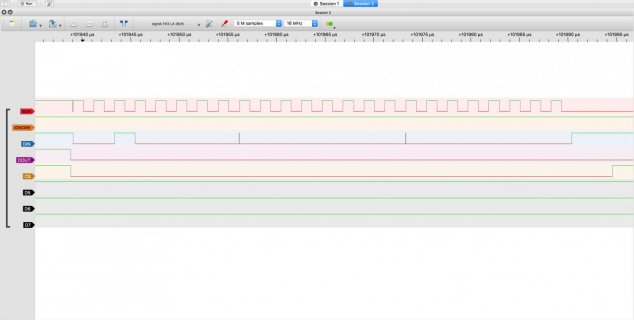
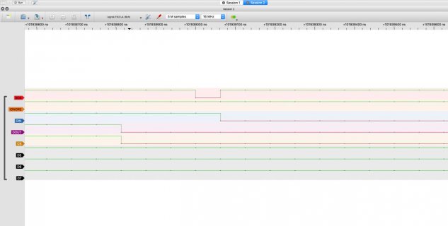
I am switching between two chips, one (ADXL312) is CPOL=1 and another (ADS1292) CPOL=0. The problem is, that the switch occurs when the data is transmitted, with SPI.transfer(), rather than when SPI.beginTransaction(settingsSpi) is called. This means that the chip select is pulled low before the clock is returned to low, and then (I believe) the chip takes this switching from CPOL = 1 to CPOL = 0 as a clock pulse, when it is not. I am not sure how to address this.

Is it possible to change the CPOL before or without transmitting any data?

I have attached some images of the data transfer, and the same transfer zoomed in. My code snippet, for reference:

Code:
registerToRead=(registerToRead|0x20);
  SPI.beginTransaction(settingsSpi);
  delayMicroseconds(5);
  digitalWrite(respPinSelect,LOW);
  SPI.transfer(registerToRead);
  SPI.transfer(B00000000); // One read to one register
  dataOut=SPI.transfer(B00000000);
  delayMicroseconds(5);
  digitalWrite(respPinSelect,HIGH);
  SPI.endTransaction();
full.jpgfull.jpgzoomed.jpg
 
I believe something similar has shown up recently. I believe it was solved (hacked around) by starting a transaction with the new setting, DON'T assert the CS, output one byte like NULL maybe end the transaction, then do your new transfer which does the normal stuff including assert the CS pin
 
If you don't want to waste cpu cycles for that additional null transaction, you might also fork the bit clock through a single inverter like the SN74LVC1G04 and feed one ic constantly with the original clock and the other with the inverted one. Thus you could do both transactions with the same polarity.
 
Sending the null data solved the problem. I'm going to test the inverter method too to save some of those cycles. This does feel like a bit of a bug though, as it should be possible to switch between chips fairly seamlessly. I tried the spi4teensy3 library too, and had the same problems.

In case anyone is interested, I modified my transaction to read data to:
Code:
SPI.beginTransaction(settingsSpi);
SPI.transfer(0x00);
SPI.endTransaction();
registerToRead=(registerToRead|0x20);
SPI.beginTransaction(settingsSpi);
delayMicroseconds(5);
digitalWrite(respPinSelect,LOW);
SPI.transfer(registerToRead);
SPI.transfer(B00000000); // One read to one register
dataOut=SPI.transfer(B00000000);
delayMicroseconds(5);
digitalWrite(respPinSelect,HIGH);
SPI.endTransaction();
 
Thanks, it will be easier for me to invert the signal rather than delve into the SPI libraries, but I would be interested to see a solution!
James
 
Status
Not open for further replies.
Back
Top