Software activation/deactivation of a CAN termination resistor (shunt)

Status
Not open for further replies.

Manu

Well-known member
Hello,

I'd like to activate/deactivate an CAN termination resistor using the software. The goal is to not put a hardware jumper and allow me to set or unset the resistor without the need to open the case.

I think I can do it like this :

CAN.jpg

ZT_ON signal is one of teensy 3.2 digital PIN (D6). U4 is an optocoupler. ZT is the resistor I want to activate/deactivate.
Can someone give me advices about this circuitry ?

Thank,
Manu
 
I'd look for an optocoupler with mosfet output, which still acts like a resistor when the voltage is low (lower than a bipolar transistor's saturation voltage). Maybe something like LCA110?

Don't forget to take the mosfet's on resistance into account. If it's 35 ohms, you'd use a ~85 ohm resistor for an effective termination of ~120 when the 2 are in series.

Don't forget a series current limiting resistor at the optocoupler input. It's just a LED, which needs current limiting just like any other LED.

A reed relay might also be worth considering. On resistance is much better than any optocoupler. If you go with a relay, don't forget the flyback diode in parallel with the coil. Even if you use a transistor to turn on the relay, that diode is needed for protection.
 
Thank to all.
Microchip solution may be a better choice than an opto for two reasons :
1 - it's more compact (less surface on the pcb)
2 - it's cheaper.

I'll update the design and post it again.
Manu
 
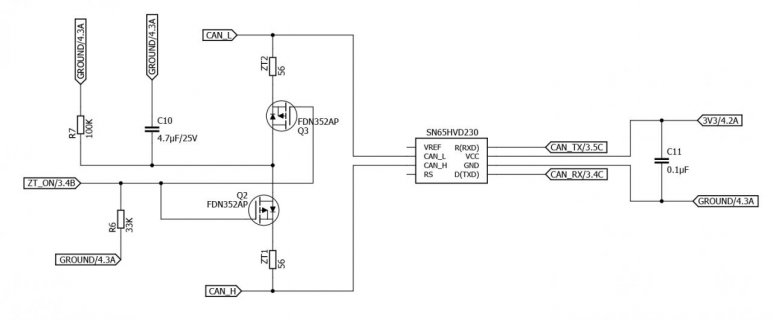
Here is the new design :

CAN_2.jpg

Is it good enough ? Or should I ad a 3V3 pullup on teensy D6 output ?

Thank,
Manu
 
Status
Not open for further replies.
Back
Top