Teensy 3.5, overclock and SPI

Status
Not open for further replies.

LuisHS

Well-known member
Hello.

Teensy 3.5 overclock to 144Mhz or 168Mhz, can it affect the operation of SPI ?.

I have problems, and I'm still not sure if it is because I have configure the clock to 144Mhz and 168Mhz. UDP communications fails with a W5500 connected to Teensy 3.5 by SPI.

regards
 
IIRC, the internal SPI module is clocked not from F_CPU, but from the (lower) system clock F_BUS which is 60MHz for F_CPU=120MHz, 56MHz for F_CPU=168MHz and 48MHz for F_CPU=144Mhz because it has always to be < 60MHz and is obtained by integer division from F_CPU.

Most SPI libraries will take your desired SPI clock and find an integer divider for F_BUS to come as close as possible (that's how the Kinetis hardware works). If you want for example a SPI clock of 6MHz, division by 10 for F_BUS=60MHz or by 8 for F_BUS=48MHz is not a problem. But with a F_BUS=56MHz will end up with "only" 5.6MHz SPI clock instead of 6MHz.

To track down your problem, I highly recommend to go back to a working CPU clock and checking the SCK, MOSI, and CS pins simultaneously with a logic analyser, and then increasing F_CPU and watch how things change.
 
OK, thanks for your reply.

Do you know if DMA is affected by the overclock ?.
I have a strange case that I do not understand.

An application, the same source code compiled for a Teensy 3.6 works perfectly, but compiled for a Teensy 3.5, some data is lost or altered. Data enters through SPI with DMA.

If I compile for Teensy 3.6, at 120Mhz, then I see the same problem. So I thought that applying an overclock to Teensy 3.5, the problem would be solved, but not, tested compiling with overclock at 144 and 168 Mhz, the problem persists, it is as if the overclock did not work and always compiled at 120Mhz for the Teensy 3.5, or the DMA do not increase speed though I apply overclock.
 
The DMA for both machines is reasonably different. Are you talking the SPI object or SPI1 or SPI2?

SPI1/2 on the T3.5 have issues with DMA, there is only one DMA Source for each of these which can either be source or target, but not both. I had to do a lot of different stuff to get the Async SPI functions to work with the T3.5.

Also there handling of data is different, the T3.6, you could play games and have an entry in the chain that output a full 32 bits to the PUSHR register and have it update the CS pins and the like. With T3.5 it did not support it, so had to find other ways to start off the transfer.

So in the SPI library code as well as when I was playing with adding frame buffer/DMA support for ili9341_t3n library, had to do other things to work around those differences.

Again hard to know without seeing exactly what your setup is. And then again I only got things to work after some trials and errors, including printing out the SPI dma chains to figure out what exactly happened...
 
The DMA for both machines is reasonably different. Are you talking the SPI object or SPI1 or SPI2?

Again hard to know without seeing exactly what your setup is. And then again I only got things to work after some trials and errors, including printing out the SPI dma chains to figure out what exactly happened...

I mean the library that is added with SPI.h.

I have already managed to optimize the source code, and it works much better, not 100%, but it has improved by 95%. Now I only lose some data from time to time, it is acceptable, although not perfect. With these modifications and the overclock to 168Mhz, it works quite well.

In any case, I think the problem is in the DMA, which is not able to capture the received data with sufficient speed. And I do not know if the overclock is capable of improving the functioning of the DMA.

This is the basic configuration that I use for SPI with DMA.

// Reloj para SPI0
SIM_SCGC6 |= SIM_SCGC6_SPI0;
SPI0_MCR = SPI_MCR_HALT | SPI_MCR_MDIS | SPI_MCR_PCSIS(1<<0);

// Transferencias de 16 bit, por señal ascendente (RISING)
SPI0_CTAR0_SLAVE = SPI_CTAR_FMSZ(15);

// Enable FIFO Drain Request DMA
SPI0_RSER = SPI_RSER_RFDF_RE | SPI_RSER_RFDF_DIRS;
dmaSPI0rx = new DMAChannel();
dmaSPI0rx->source((volatile uint16_t&) SPI0_POPR);

// Asigna buffer al DMA
dmaSPI0rx->destinationBuffer(plane_buffer, 16);

// Activa SPI-DMA
SPI0_MCR &= ~SPI_MCR_HALT & ~SPI_MCR_MDIS;
digitalWriteFast(DMD_CS, LOW);
NVIC_ENABLE_IRQ(IRQ_PORTB);
dmaSPI0rx->enable();
 
Note: Some of my DMA SPI work is a bit rusty. Likewise the use of it with Slave code.

First overclocking to 168mhz, not sure if that helps you or hurts you. If your actual code running needs the higher speed than maybe helps. However for SPI...
If I remember correctly SPI object (SPI0) uses F_BUS to control it's speed.
By default if your run the T3.5 at the default 120mhz, by default the system will set F_BUS to 60mhz.
If you run at 168mhz F_BUS is set to 56MHZ

If I remember correctly the max SPI transfer rate is 1/2 of F_BUS so at 120 mhz max is 30mhz and 168 it is 28mhz ...

As for DMA, I am pretty sure it should not have an issue.

If I were guessing, I would be wondering about when is the data lost? I don't see anything here on how you use your plane-buffer and know when the DMA completes. All I can see is you have it setup to probably read 16 items.
Is there an interrupt when it completes? And/or an interrupt set at half way point? Do you read more than these 16 items? Maybe lost data in between these? If continuous processing, If it were me, might look into circular buffer or chaining two DMA TCD structures to each other, and set interrupts at completion, such that DMA is set to continue at all times... But again don't know your requirements and/or where maybe something is going wrong.

Good luck. Sorry probably not much help here.
 
.

There is an external trigger signal for an interrupt that run a function where I do a memcpy to copy the DMA buffer to an array. I think it's here, when I do the memcpy, I lose some data, but I'm not sure if DMA was not so fast to capture all the data or if my program does not arrive in time to copy the data from the DMA buffer. After optimizing the source code, I managed to improve it a lot, but not totally, the result is now acceptable, but not perfect.

At any rate with same source code, works fine with Teensy 3.6, even at 144Mhz, but fail with Teensy 3.5 even with 168Mhz overclock. With Teensy 3.6 at 120Mhz also fail. The strange is that with same clock frequency, 144 or 168 Mhz, works with Teensy 3.6, and fail with Teensy 3.5.


Source code to Configure interrupt to copy the DMA buffer to a work array.

attachInterrupt(digitalPinToInterrupt(DMD_ROW_DATA), portb_isr_spike, RISING); // Inicio de FRAME
attachInterrupt(digitalPinToInterrupt(DMD_DOT_LATCH), portb_isr_spike, RISING); // Inicio de Linea, OK.
attachInterruptVector(IRQ_PORTB, portb_isr_spike); // Replace global PORTB isr


Part of the Source code in the interrupt function to copy DMA buffer

// Captura datos de linea (128 puntos) por DMA
memcpy(wpc_planes[plane][row], plane_buffer, 16); // Copia buffer DMA a matriz planos
digitalWriteFast(DMD_CS, HIGH); // Use fake chip select to end plane

// Reinicia DMA para siguiente captura de linea
// Flush the receive buffer, in case we're out of sync
SPI0_MCR |= SPI_MCR_HALT;
SPI0_MCR |= SPI_MCR_CLR_RXF;

// Reset the DMA transfer
dmaSPI0rx->disable();
dmaSPI0rx->clearComplete();

dmaSPI0rx->destinationBuffer(plane_buffer, 16);
dmaSPI0rx->enable();

// Start new SPI plane
SPI0_MCR &= ~SPI_MCR_HALT;
digitalWriteFast(DMD_CS, LOW);


.

One more question.
What is difference between attachInterruptVector and attachInterrupt ?

For example in this source code, Im not sure that really need the last line, and if I can replace the two first lines, to run each one a different function for each interrupt.

attachInterrupt(digitalPinToInterrupt(DMD_ROW_DATA ), portb_isr_spike, RISING);
attachInterrupt(digitalPinToInterrupt(DMD_DOT_LATC H), portb_isr_spike, RISING);
attachInterruptVector(IRQ_PORTB, portb_isr_spike); // Replace global PORTB isr
 
With some of your stuff, maybe the memcpy is taking awhile to complete, maybe other interrupts with higher priorities (lower number) happen... That causes you to not receive some data...

Again if it were me, would probably setup to look using logic analyzer... And depending on the actual data and how it is to be used...

If continuous data, I would probably setup to continuously read in two buffers chained to each other, and set ISR to happen on each one. So when it completed the 16 words, it was still setup to receive the next word, regardless of how long it took to service the interrupt...

Or if not continuous, and you do need the stop and change of CS pins.... I would probably have the DMA set with the interrupt on completion as well as the disable on completion set.... I also might see if i could avoid using memcpy. Like can I setup the destination buffer to be to the wpc_planes[plane][row] that it would be copied to...

Difference between attachInterrupt and attachInterruptVector. attachInterrupt is for a specific pin. The system sets up some default interrupt handlers for the different ports, and it enables the specific one that is associated with your IO pin you called it with. When the IO pin changes state to cause an interrupt, the systems handler is caused, which services all of the IO pins associated to the IO port, and it determines if the interrupt was caused by Your pin and then it calls your handler for that io pin...

The attachInterruptVector, set the actual system function that is called for the specific interrupt. In your case it sets the IRQ_PORTB interrupt in the RAM based system Interrupt Vector, to point to the ISR function you mentioned... This may be for IO pins, or my be a DMA interrupt, or USart or ...

Kurt
 
.

Okay thanks.
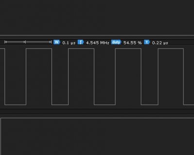
Some time ago I measured with the logic analyzer, it was the clock frequency, 0.1us, 4.54 Mhz. It may be very fast for the Teensy 3.5 DMA.

screenshot2.jpg

The data is continuous in this application, it never stops, I must constantly receive 16 bytes, 32 times, this is a frame for a LED screen that shows animations. Several frames make an image, in this case 4 frames are mixed to make an image, and the machine sends 4 frames with different times, 1ms, 2ms, 4ms and 8ms, each with 32 rows of 128 points.

There are several manufacturers, all work well, except this one with a very fast clock.
 
4.5mhz is not that fast... We sometimes drive ili9341 SPI display at 30mhz. And DMA can go very fast, and also noting that SPI interface you have 16 bits of data come in for each word that is transferred...

So again I would assume more of a timing issue. But could be wrong... Maybe someone else has other insights?

Things like, maybe set the DMA channels interrupt to higher priority (lower number?)
I think that can be done by doing something like: NVIC_SET_PRIORITY(IRQ_DMA_CH0+dmaSPI0rx.channel, 32);
Again not sure what values to try...

Or again maybe setup to read whole frame in, which sounds like 32*16=512, which again should be possible here.
I do full dma of an ILI9341 display which is 320*240*2= 153,600 bytes but for this we can not do one TCD setup, max like 64K, so we have it
TCD structures link with three entries linked to each other, to do the whole thing in one DMA transfer.
 
.

With the optimization of the source code that I made, plus the overclock to 168Mhz, it has improved a lot. Basically, I modified the program so that as soon as the interrupt occurs, the first thing to run is the memcpy, to immediately capture the DMA buffer. Before modifying it there were some IF before the memcpy, which could be delaying the copying of the buffer data to my work array, losing some data.

That's why I also wanted to try to modify the interrupts, since as it is, it jumps to the same function with two different interrupts, and then in the function there is an IF that checks if the interrupt was by one of the signals, and then there was another IF that checked if the interrupt was by the other signal.

In the original source it was like this:

attachInterrupt(digitalPinToInterrupt(DMD_ROW_DATA), portb_isr_spike, RISING);
attachInterrupt(digitalPinToInterrupt(DMD_DOT_LATCH), portb_isr_spike, RISING);
attachInterruptVector(IRQ_PORTB, portb_isr_spike);


And the idea is to leave it that way, with two separate functions for each signal, so I eliminate the two IFs that then select each signal in the same function. What I do not know is what the IRQ_PORTB is for, and if I can remove it, I have deleted it, but I have not yet tested if it works.

attachInterrupt(digitalPinToInterrupt(DMD_ROW_DATA), portb_isr_spike_f, RISING);
attachInterrupt(digitalPinToInterrupt(DMD_DOT_LATCH), portb_isr_spike_l, RISING);
 
Status
Not open for further replies.
Back
Top