Simultaneous RFID Reader Serial Communication to Teensy 3.2

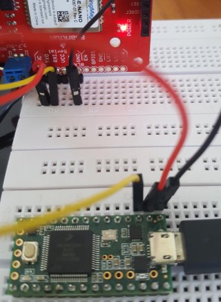
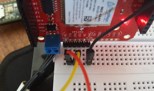
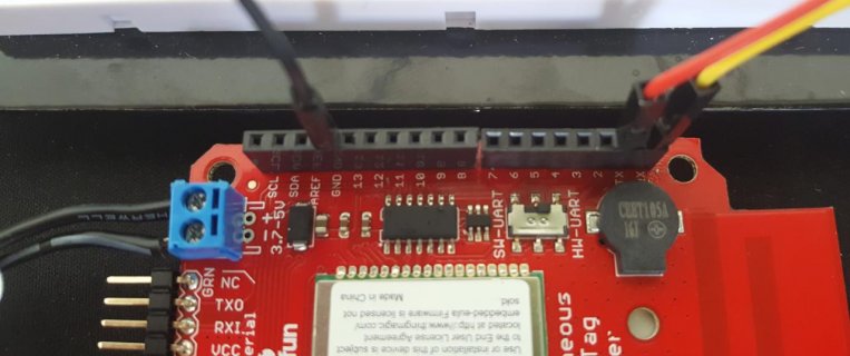
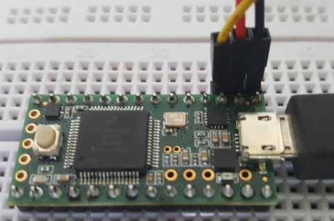
I'm using the SparkFun Simultaneous RFID Reader and would like to communicate over hardware serial with a Teensy 3.2. I successfully tested the reader as a shield with an UNO, using an example sketch that talks to the UNO over software serial. I've taken that example sketch and replaced usage of SoftwareSerial with Serial1 and wired things as shown in the photos.
20180829_120145.jpg20180829_120205.jpg

Here is the sketch, where I've replaced SoftwareSerial with Serial1:

Code:
/*
  Reading multiple RFID tags, simultaneously!
  By: Nathan Seidle @ SparkFun Electronics
  Date: October 3rd, 2016
  https://github.com/sparkfun/Simultaneous_RFID_Tag_Reader

  Constantly reads and outputs any tags heard

  If using the Simultaneous RFID Tag Reader (SRTR) shield, make sure the serial slide
  switch is in the 'SW-UART' position
*/


#include "SparkFun_UHF_RFID_Reader.h" //Library for controlling the M6E Nano module
RFID nano; //Create instance

void setup()
{
  Serial.begin(115200);
  while (!Serial); //Wait for the serial port to come online

  if (setupNano(38400) == false) //Configure nano to run at 38400bps
  {
    Serial.println(F("Module failed to respond. Please check wiring."));
    while (1); //Freeze!
  }

  nano.setRegion(REGION_NORTHAMERICA); //Set to North America

  nano.setReadPower(500); //5.00 dBm. Higher values may caues USB port to brown out
  //Max Read TX Power is 27.00 dBm and may cause temperature-limit throttling

  Serial.println(F("Press a key to begin scanning for tags."));
  while (!Serial.available()); //Wait for user to send a character
  Serial.read(); //Throw away the user's character

  nano.startReading(); //Begin scanning for tags
}

void loop()
{
  if (nano.check() == true) //Check to see if any new data has come in from module
  {
    byte responseType = nano.parseResponse(); //Break response into tag ID, RSSI, frequency, and timestamp

    if (responseType == RESPONSE_IS_KEEPALIVE)
    {
      Serial.println(F("Scanning"));
    }
    else if (responseType == RESPONSE_IS_TAGFOUND)
    {
      //If we have a full record we can pull out the fun bits
      int rssi = nano.getTagRSSI(); //Get the RSSI for this tag read

      long freq = nano.getTagFreq(); //Get the frequency this tag was detected at

      long timeStamp = nano.getTagTimestamp(); //Get the time this was read, (ms) since last keep-alive message

      byte tagEPCBytes = nano.getTagEPCBytes(); //Get the number of bytes of EPC from response

      Serial.print(F(" rssi["));
      Serial.print(rssi);
      Serial.print(F("]"));

      Serial.print(F(" freq["));
      Serial.print(freq);
      Serial.print(F("]"));

      Serial.print(F(" time["));
      Serial.print(timeStamp);
      Serial.print(F("]"));

      //Print EPC bytes, this is a subsection of bytes from the response/msg array
      Serial.print(F(" epc["));
      for (byte x = 0 ; x < tagEPCBytes ; x++)
      {
        if (nano.msg[31 + x] < 0x10) Serial.print(F("0")); //Pretty print
        Serial.print(nano.msg[31 + x], HEX);
        Serial.print(F(" "));
      }
      Serial.print(F("]"));

      Serial.println();
    }
    else if (responseType == ERROR_CORRUPT_RESPONSE)
    {
      Serial.println("Bad CRC");
    }
    else
    {
      //Unknown response
      Serial.print("Unknown error");
    }
  }
}

//Gracefully handles a reader that is already configured and already reading continuously
//Because Stream does not have a .begin() we have to do this outside the library
boolean setupNano(long baudRate)
{
  nano.begin(Serial1); //Tell the library to communicate over software serial port

  //Test to see if we are already connected to a module
  //This would be the case if the Arduino has been reprogrammed and the module has stayed powered
  Serial1.begin(baudRate); //For this test, assume module is already at our desired baud rate
  while(!Serial1); //Wait for port to open

  //About 200ms from power on the module will send its firmware version at 115200. We need to ignore this.
  while(Serial1.available()) Serial1.read();
  
  nano.getVersion();

  if (nano.msg[0] == ERROR_WRONG_OPCODE_RESPONSE)
  {
    //This happens if the baud rate is correct but the module is doing a ccontinuous read
    nano.stopReading();

    Serial.println(F("Module continuously reading. Asking it to stop..."));

    delay(1500);
  }
  else
  {
    //The module did not respond so assume it's just been powered on and communicating at 115200bps
    Serial1.begin(115200); //Start software serial at 115200

    nano.setBaud(baudRate); //Tell the module to go to the chosen baud rate. Ignore the response msg

    Serial1.begin(baudRate); //Start the software serial port, this time at user's chosen baud rate
  }

  //Test the connection
  nano.getVersion();
  if (nano.msg[0] != ALL_GOOD) return (false); //Something is not right

  //The M6E has these settings no matter what
  nano.setTagProtocol(); //Set protocol to GEN2

  nano.setAntennaPort(); //Set TX/RX antenna ports to 1

  return (true); //We are ready to rock
}

On line 22, the call to
Code:
setupNano(38400)
fails, returns false, and the sketch stops at the infinite loop placed in line 25, after printing "Module failed to respond. Please check wiring."

This is my first attempt at hardware serial, so I'm not confident in my code or wiring to be honest.
 
Incorrect. Maybe you saw a bunch of references to Serial and stopped reading? Check lines 101, 105, 106, 109, 125 and 129. I probably should have pointed them out.
 
you are actuallly supposed to do nano.begin(Serial1) and then do nano.baud(38400), sorry i see now you used Serial1 way below in sketch, use nano.begin(Serial1) first :)

looks like ur doing it right, might just be a library issue
 
try to use another GND pin on that board, some pins are just “pass-through” from the host, you never know with all breakouts. I seen boards do this
 
Awesome, thanks for taking another look. I think the setupNano function places them in that order. When you say a library issue, you mean the library for the reader itself?

EDIT: Just tried the other two ground pins, no luck, but good idea to try.

I'll hit up SparkFun and see if they can confirm the HW-UART switch does what I think it does and that this ought to work (they said in their first reply that they don't support the Teensy, but I figure they can at last confirm the HW serial part).
 
im on my phone so its hard to help, or look at its eagle files, but on their site, i check front and back of that board with zoom, i dont see a trace of that pin being brought out, pretty sure it’s pass through
 
if you look at BZ1 and BZ2 in back of PCB, you will see a trace going out of them, they most likely would be the correct place to put the ground wire between the module and teensy’s GND, BZ1 and BZ2 on other side of PCB are the 2 ground points of many arduinos
 
Maybe try swapping the yellow and red wires?

The printing on Sparfun's board seems confusing. It shows "TX" on pin 1 where the red wire is connected, and "RX" on pin 0 where the yellow wire is connected. But those probably are not how this shield actually works. Those are probably just a copy of the labels printed on Arduino Uno. Uno & Teensy transmit on pin 1. This shield almost certainly receives on pin 1, even though the printing says "TX". Likewise for pin 0, Uno & Teesny receive on pin 0, so this shield probably transmits on pin 0, even though the label says "RX".

If the printing on the shield accurately documented the way it really works, then the way you connected the wires would be correct. But the printing is (probably) wrong for this shield.

Connect pin 0 from the shield to pin 0 on Teensy, and pin 1 to pin 1.
 
I tried swapping the wires, to no avail.

This is the response I got from SparkFun:

"The switch just selects which pair of shield pins the module is connected to. HW-UART connects the module to pins 0 and 1 while SW-UART connects the module to pins 2 and 3. You can also bypass the switch all together by using the RX/TX and GND pins that are on the ‘Serial’ header at the top of the board..."

So I tried using the pins at the top of the board, same issue. Photo attached. I tried with a Teensy LC in case the micro had been damaged, but no change there either.

20180829_151617.jpg20180829_151628.jpg
 
That connection looks correct. The signal names line up properly with the FTDI serial cable I have here.

Why it's not working, I do not know.

I noticed this in the software:

//About 200ms from power on the module will send its firmware version at 115200. We need to ignore this.

As a sanity check, maybe try programming Teensy with File > Examples > Teensy > USB_Serial > USBtoSerial.

Then in the Arduino IDE, select the port from the "Serial" part of the Ports menu (not from the "Teensy" part) so Arduino will treat it like a normal serial device. Open the serial monitor and select 38400 baud (when using the Teensy-specific serial monitor, there's no baud rate selection).

While the serial monitor is open, try power cycling the shield. When it sends this info, you should see it appear in the serial monitor. That would at least be a confirmation the shield is booting up and data is able to from in the shield-to-Teensy direction.
 
When I try running the USBtoSerial example I get the single character 'C' in the Serial Monitor, when the reader is first powered on. I don't know if that is a proper interpretation of the firmware version, but it is something!
 
Ok, this is a long shot, but try checking those breakboard wires with a multimeter (in ohms or beeper mode). It's rare, but we have seen cases where a project didn't work due to a broken connection in those types of wires.
 
Do you have a scope or analyzer you can hook to Serial1 Tx and Rx? It looks like you have a common GND between Teensy and shield.
 
Do you have a scope or analyzer you can hook to Serial1 Tx and Rx? It looks like you have a common GND between Teensy and shield.

I don't have a scope myself, but might be able to get access to one. What would I look for? Wires are good according to my meter and the same wires work with the Arduino UNO when testing over SoftwareSerial.

I inserted a statement to print the error condition out before it fails. The error code is '3', defined in the library as
Code:
ERROR_WRONG_OPCODE_RESPONSE
The library compares the opcode sent with the outgoing message to the opcode in the reply. If they are not identical it it results in this error. If I remove a wire, or reverse them, I get
Code:
ERROR_COMMAND_RESPONSE_TIMEOUT
So, it appears that there is data coming from the reader in the first case, it just isn't what is expected. Could this imply a baud-rate mismatch? I'm actually not totally clear on how this code properly negotiates the baud-rate if it isn't right to begin with.
 
since you're not using software serial, you could leave the baudrate at its faster default setting.
 
Hi Guys, i got it woking.
Way overtime but could be of use to someone.

here is what you should do:
-connect via Serial pins TXD RXI,
-Vin of the sparkfun board at 3,7V
-Arduinocode: example hardware Serial. change every hardware serial5 to 1.

rocknroll.

i havent got it working at 5v. my lvl shifter isnt working.
 
Back
Top