Good day everybody!
After having done a few projects with Arduino (one of them with ~35 inputs/outputs on the Arduino MEGA) I recently decided to go ahead with the Teensy 3.5, however 3.3V logic level is virgin soil for me and I am kind of chicken-hearted of doing something that could damage it. I am not an engineer, so please be patient with my following thoughts.
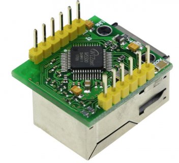
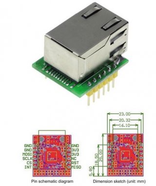
I would like to change my MEGA with the Teensy 3.5 (which is installed abroad and runs over a year now), improve a few things and add three modules I don't have any experiences with. Now, the normal procedure would be to start on a breadboard one after another, but in this case I have to plan the basis of the circuit before (yes, that's another risk). Most of the sensors already in use are 3.3-5V tolerant and I tried them out without having difficulties (such as the DHT, DS18B20, PIR sensors, simple switches and potentiometers), BUT two modules are new for me (USR-ES1 W5500 Ethernet Module, INA219 I2C Current Module) and they are on its way. Before connecting them I would like to know if I prepared the connections correctly and if my plan with a Buck Converter doesn't do any harm to the battery bank of the solar system (24V, 500Ah). Would somebody with experience please be so kind and look over this circuit?
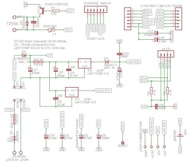
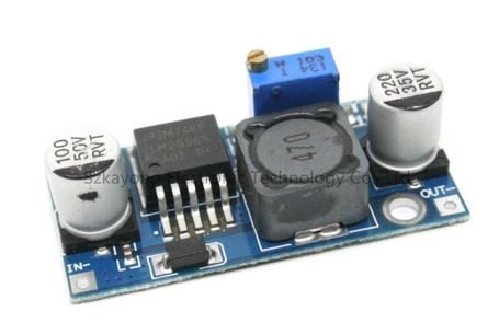
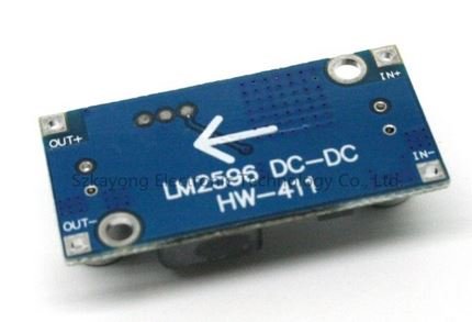
1.) The whole project will be connected to a 24V solar battery. As voltage varies between 23 and 29 volts (depending on the charging state) I decided to use a DC-DC-Buck Converter first (7-30V, 3A max.). It's input/output is protected with a fuse against short circuits and a diode if any draw back occurs.
2.) Then two separate LM1117 will be used (my first time also): 5V for the Teensy 3.5 only and another one with 3.3V for the Ethernet Controller only (I was said in this forum that the Ethernet shield draws quite a lot energy, so I thought it might be best to get a linear voltage regulator just for this module with two additional 470uF capacitors). Both output voltages with have a 470uF and 0.1uF capacitor.
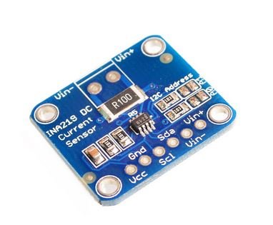
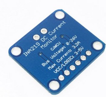
3.) The INA219 Current Sensor module is placed right after the Buck Converter that should have 11 to 12 volts at its output to measure the total current. Before mounting together these parts I will cut the VIN from VUSB on the bottom of the Teensy.
4. The USR-ES1 W5500 Ethernet Module is connected with the pins: 10-CS0, 11-MOSI0, 12-MISO0, 13-SCK0 and RESET with Reset of the Teensy. NC and NINT are not connected (what is the purpose of NINT anyway?).
It would be brilliant to replace the small 0.96" OLED in the long run with the 1.8" Adafruit ST7735 Color TFT 128x160px display that has an additional SD card slot. Maybe in this planning phase it would be a good idea to verify the correct pin assignment right at the start - without having to solve troubles afterwards with any other module mentioned above: 13-SCLK, 11-MOSI, 2-CS_tft, 9-DC, 8-RST and 28-CS_sd Is this correct?
Thank you very much for your help!
Dragonfly
After having done a few projects with Arduino (one of them with ~35 inputs/outputs on the Arduino MEGA) I recently decided to go ahead with the Teensy 3.5, however 3.3V logic level is virgin soil for me and I am kind of chicken-hearted of doing something that could damage it. I am not an engineer, so please be patient with my following thoughts.
I would like to change my MEGA with the Teensy 3.5 (which is installed abroad and runs over a year now), improve a few things and add three modules I don't have any experiences with. Now, the normal procedure would be to start on a breadboard one after another, but in this case I have to plan the basis of the circuit before (yes, that's another risk). Most of the sensors already in use are 3.3-5V tolerant and I tried them out without having difficulties (such as the DHT, DS18B20, PIR sensors, simple switches and potentiometers), BUT two modules are new for me (USR-ES1 W5500 Ethernet Module, INA219 I2C Current Module) and they are on its way. Before connecting them I would like to know if I prepared the connections correctly and if my plan with a Buck Converter doesn't do any harm to the battery bank of the solar system (24V, 500Ah). Would somebody with experience please be so kind and look over this circuit?

1.) The whole project will be connected to a 24V solar battery. As voltage varies between 23 and 29 volts (depending on the charging state) I decided to use a DC-DC-Buck Converter first (7-30V, 3A max.). It's input/output is protected with a fuse against short circuits and a diode if any draw back occurs.
2.) Then two separate LM1117 will be used (my first time also): 5V for the Teensy 3.5 only and another one with 3.3V for the Ethernet Controller only (I was said in this forum that the Ethernet shield draws quite a lot energy, so I thought it might be best to get a linear voltage regulator just for this module with two additional 470uF capacitors). Both output voltages with have a 470uF and 0.1uF capacitor.
3.) The INA219 Current Sensor module is placed right after the Buck Converter that should have 11 to 12 volts at its output to measure the total current. Before mounting together these parts I will cut the VIN from VUSB on the bottom of the Teensy.
4. The USR-ES1 W5500 Ethernet Module is connected with the pins: 10-CS0, 11-MOSI0, 12-MISO0, 13-SCK0 and RESET with Reset of the Teensy. NC and NINT are not connected (what is the purpose of NINT anyway?).
It would be brilliant to replace the small 0.96" OLED in the long run with the 1.8" Adafruit ST7735 Color TFT 128x160px display that has an additional SD card slot. Maybe in this planning phase it would be a good idea to verify the correct pin assignment right at the start - without having to solve troubles afterwards with any other module mentioned above: 13-SCLK, 11-MOSI, 2-CS_tft, 9-DC, 8-RST and 28-CS_sd Is this correct?
Thank you very much for your help!
Dragonfly


