Teensy 3.2 Breakout Board with CAN transceiver Design Question

Status
Not open for further replies.

mjs513

Senior Member+
Hi All

Just for the heck of it I put together a small breakout board designed around the T3.2 with a SN65HVD230 CAN transceiver. That part of the circuit is based on the Waveshare mini-breakout board:
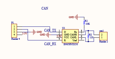
WaveshareMiniCanBreakout.PNG
I already have 4 of them and they work well but wanted to incorporate one onto at the board level. The schematic for the board is:
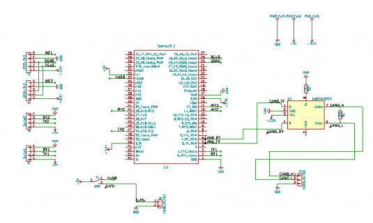
T32-CANbus.PNG
I had a few PCBs made and was just testing it but for some reason it is not reading packets coming to it. I checked the circuit with a multimeter to make sure connections were going where they were suppose to according the schematic. But no dice. Did check the voltage to make sure it was getting power to chip, and it was.

Below is a photo of the board:
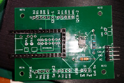
20180912_182813.png

If anyone has any ideas it would be appreciated. Because I can't see what I am missing.

Thanks
Mike
 
For testing, do You connect two or more boards ?
In my waveshare breakouts there is a 120 Ohm resistor in each board, and the Jumper is not for enabling or disabling it. Only two of these termination resistors are allowed on the can-bus. For using more than two of these breakouts I had to desolder the resistor.

Also these TexasInstruments(?, I dont know if they are genuine on Waveshare boards) Transceivers seemed to be very sensible, on some of my test-Setups I had to put my finger accross the Pins of the Transceiver to start communication, some week PullUp through my fingers……
At the Moment I want to make a PCB as well and i will test Microchip and NXP (TJA.....) Receivers.
 
Hi AutoMike,
Welcome to the forum. As for your questions:

For testing, do You connect two or more boards ?
For testing I am only using two boards. One is the waveshare and the other is my version.

Only two of these termination resistors are allowed on the can-bus. For using more than two of these breakouts I had to desolder the resistor.
Believe it or not I have had 3 running at one time all with the 120ohm resistor in place and it worked fine. I have tested my design with and without the resistor in place.

Transceivers seemed to be very sensible, on some of my test-Setups I had to put my finger accross the Pins of the Transceiver to start communication, some week PullUp through my fingers……
Didn't try that one. Maybe I will give it a try just for the heck of it. On the tx/rx pins or the canh/canl pins?

Getting ready to run a test with the MCP2551 in place just as a test. They should be drop in compatible.

Keep us posted on how your design is progressing. Thanks for getting back to me.


v/R
Mike
 
I changed to the MCP2551 and circuit still didn't work. Something is wrong somewhere and just don't where
 
The MCP2551 is a 5V part. Did You Change the VDD-voltage ? Also I don't know if the Transceiver will recognize the correct Level when used with a 3,3V Output by the teensy.
On my PCB I plan to use a MCP 2562FD-E/SN. It has 5V power supply but on Pin5 You provide the reference I/O voltage to use with a 3,3V microcontroller.
 
Thanks AutoMike - yep I rewired the 3.3v to the 5v pin. Forgot to mention that but finally figured out my problem. For the MCP2551 I actually used a MCP2515 and was using the wrong chip in for the ti sn65. I had the parts in the wrong bags. I ordered some new ones from Digikey - won't have until next week though. So it should work.
 
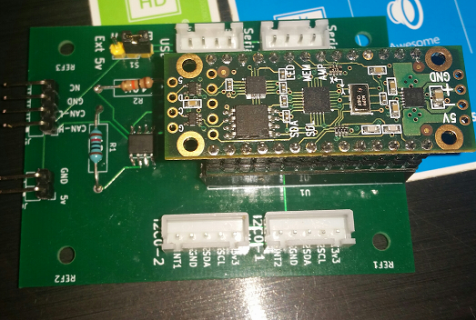
Hi all. Now that I am using the correct transceiver, I tested it today and its working fine. Here is picture of what the board is suppose to look like when it is loaded. Right now it has the T3.2 with a propshield attached;
2018-09-19 19.58.48.png
 
Status
Not open for further replies.
Back
Top