MPU-9250 SPI in BASIC

Status
Not open for further replies.
I hadn't bothered with the magnetometer on the MPU-9250 since I was interested in high rate gyro data and a previous bad experience with the MPU-9150.

When using an SPI interface with the MPU-9250 like I am (I2C can't support 32KSPS gyro data.) you need to use the slave controller to access the magnetometer.

I setup two I2C slave controller channels. The first (slave 0) is configured to read the results while the second sends the command to start a conversion. This runs at the sample rate so the sample rate must be 100Hz or less.

I like to use a table of register number/value pairs to initialize:
Code:
  0 \ mpu-9250 init table for magnetometer use            23Sep2018             
  1 VARIABLE INIT-TAB                                                           
  2    106 , $10 ,        \ disable I2C slave interface                         
  3    107 ,   1 ,        \ use gyro as clock source (1%)                       
  4     25 ,   9 ,        \ sample rate divider = 10                            
  5     26 ,   5 ,        \ gyro DLPF is 10Hz                                   
  6     27 ,  $8 ,        \ 1KHz sample rate,  500 dps                          
  7     28 , $18 ,        \ accel range = 16G                                   
  8     29 ,   5 ,        \ 1KHz sample rate, DLPF = 10Hz                       
  9     55 , $30 ,        \ int pin is active high till cleared                 
 10     56 ,   1 ,        \ enable data ready interrupt                         
 11                                                                             
 12 ( Configures the gyros and accels for 100SPS and uses the                   
 13   I2C master controller to capture data from the magnetic                   
 14   sensor. )                                                                 
 15
  0 \ MPU-9250 init table for magnetometer, cont.         23Sep2018             
  1    37 , $8C ,          \ read from slave address $C                         
  2      38 ,   2 ,          \ start at register 2 (status 1)                   
  3      39 , $88 ,          \ 8 registers read, at the sample rate             
  4      40 , $C  ,          \ write to slave address $C                        
  5      41 , 10  ,          \ to control register                              
  6      42 , $81 ,          \ 1 byte, at sample rate                           
  7     100 , $11 ,          \ single conversion mode, 16 bit                   
  8      36 , $4D ,          \ wait for slave data before data ready            
  9     106 , $20 ,          \ enable I2C master                                
 10                                                                             
 11  HERE INIT-TAB - 1 CELLS / 2/ INIT-TAB !                                    
 12                                                                             
 13                                                                             
 14                                                                             
 15
This is in Forth but you should be able to get the point. (numbers with a leading "$" are base 16 while the others are base 10.)

After doing that the magnetometer will make a conversion at the sample rate and the results will be moved to the slave data registers (73+). Where it can be read along with the rest of the data.

I captured a little data just to see if the 9250 really had improved on the magnetometer in the 9150. It is better but still not great. The useful range is improved (at least when using the 16 bit conversion mode) but the noise is still excessive. If you want to get decent results for something like a compass you will have to run the data through a low pass filter.

The initial offset is also large. Since that isn't stable, you will have to do periodic recalibration.
 
Hi U,
Thanks a lot, much appreciated.
However, my skill level is pretty poor, and even though I can almost see what's happening, it is probably too difficult.

I'll have a go and report back.
C.


C.
 
Look through the begin method in the MPU9250 class. You likely are not using the FIFO, but are instructing the MPU9250 to gather 7 bytes of data from the magnetometers at the sample rate (likely 100 Hz):
https://github.com/bolderflight/MPU9250/blob/master/src/MPU9250.cpp#L157

That data will show up in the EXT_SENS_DATA_00 through EXT_SENS_DATA_06 registers and will automatically be updated at the sample rate. You can burst read those registers when reading from the MPU-9250 (i.e. read all 7 in a single transaction).

Just want to bring to your attention that my code is running without any issues but after sometime, I am getting all zero's from EXT_SENS_DATA_00-EXT_SENS_DATA_06 registers which carry magnetometer readings.
Does anyone have any idea where the things could go wrong?

If I restart my MPU9250 then everything starts to work again as usual. But when this 'lock up' happens, nothing is helping to get out of that state such as re-initializing the device or even rebooting the MCU.

My point is since this is working for some time, basic set up seems to be correct, but after some time for some reason giving all zero's and a power cycle seems to be fixing the issue? Does this sounds like an issue with the MPU9250 itself?

Appreciate your help.
 
Hi L,

I can see that you are having difficulties, running your modules, I also had difficulties, so I looked for yet another module.

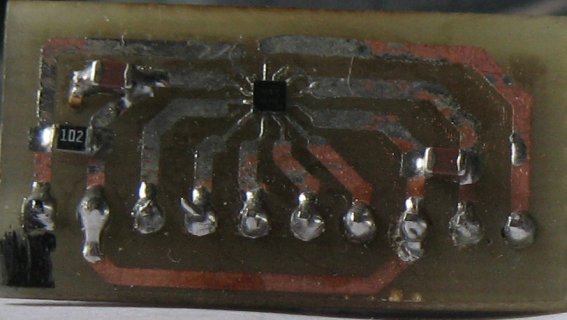
After a search and many failed tests of modules, I found the I-phone compass module AK8963C. They come on breakout boards, but they are a bit too expensive for me, so I bought the chips, and made my own breakout boards. This is challenging as they are tiny, but I succeeded and find them fine.

Thanks for all of the contributions, C.
 

Attachments

  • AK8963C BREAK OUT BOARD.jpg
    AK8963C BREAK OUT BOARD.jpg
    186.2 KB · Views: 77
Yes, it sounds like an I2C line on the MPU-9250 is getting held. On Teensy we have options to reset the bus, but the MPU-9250 doesn't have those options. Resetting and re-initializing won't work, because the AK8963 is still just sitting on the I2C bus waiting. I had similar issues until I figured out how to carefully shutdown the AK8963 and bring it back up during my begin method. Before that, users had to reset power if they uploaded a new sketch.
 
Yes, that's what I was wondering too... but since the I2C we're talking about is the internal I2C bus of MPU9250, there's no way that from MCU via SPI we could reset the internal I2C bus once it is in 'locked' status unless we power cycle the MPU9250.

I would like to get any insight from vendor InvenSense if there's any workaround through software rather than power cycling the module. Let me write to them too, also feel free if you guys have any other ideas.

Yes, I found no work around if their bus locked. My only solution was to carefully design how my program started talking to the MPU-9250 (since, in an Arduino environment, the sketch could have been flashed with a previous sketch already running and the MPU-9250 sampling the magnetometers) and it's been pretty robust since. Seems like a silly design choice, the AK8963C has a reset pin, but the MPU-9250 doesn't break it out. Good luck, hope you get feedback from Invensense.
 
Exactly, it's silly that not exposed the RST pin on MPU9250. I'll keep you guys posted with what I'm hearing from the vendor.
 
According to the MPU9250 block diagram the I2C connection to the internal slave should be visible from the MPU9250 aux I2C pins. Monitoring that might give you some insight into where the problem starts.
 
Status
Not open for further replies.
Back
Top