I've been exploring piezo triggering with the Teensy 3.2 board (yes, yet another piezo project), and am seeing strange behavior with noise on the analog signal line and/or grounding issues. Basically, in quiescent mode (no tapping on box with piezo attached), and after a reboot, I see 30-40 mV of noise. However, most of the time, after a tap (light, medium, heavy, doesn't really matter though happens more often with heavy tap) the quiescent noise jumps to 90-100 mV and stays that way until I reboot the Teensy, whereupon the quiescent noise goes back to 30-40 mV. This occurs with the Teensy board connected (and powered) via a Raspberry Pi (3B+) and I also get similar results when connected via USB to a fully loaded (hardware and software) desktop Windows 10 PC.
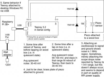
Here is a diagram of the circuit I'm using:

If I hook up an oscilloscope, attaching leads to the signal line and ground, I see noise in the 1 MHz range (and some 60 Hz noise too). Interestingly enough, sometimes the mere attaching of the oscilloscope drops the noise to an average 10 mV and sometimes all the way down to 1 mV. Also, connecting the ground of my circuit to a direct ground on the oscilloscope can at times instantly drop the noise though not always. This can happen even with the scope not even turned on (but still plugged into the wall socket). So clearly, there is some grounding phenomenon going on.
One question I have about the use of the ground pins on the Teensy 3.2 board: I'm using the Agnd pin as suggested by other posts in this forum (and perhaps I read this elsewhere too) and the reference manual for the MCU seems to suggest this as well, but frankly, I find the ground pin on the opposite set of pins (the "digital side"), as shown in the diagram above to be quieter, and I've also experimented with tying these grounds together, though I think I read somewhere this may not be a good idea. Either way, I get the same strange behavior. So what is the official recommendation for the use of these ground pins? I know that's been answered before in this forum but I'm just looking for a good, clear confirmation of the recommended approach. As far as the signal conditioning in the circuit, I experimented with 10K, 20K, 47K, 100K and 1M and 2M ohm load resistors on the (35mm size) piezo, and found that the 1M ohm resistor appears to give the best SNR. I'm using diode clamping as well.
Here is the code I'm using (I have the Teensyduino sketch type set to "Serial"). In this code, I find the peak and average voltages read on the A0 pin using sample sizes of 50,000 samples per set, and then spit the results out to the serial port and display them on the serial monitor. This is done repeatedly:
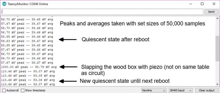
And here is a snapshot of the serial monitor window during a sample run, where you can see the quiescent noise jumping to 90-100 mV after a slap on the wood box the piezo is attached to. The noise stays in that range (remember, I'm taking statistics of 50K samples/set over and over) until the next reboot, whereupon the noise goes back to 30-40 mV:

Any advice is greatly appreciated, and I have to say I'm enjoying using this board. Just wish I could figure out how to correct the aforementioned problem.
Bryan
Here is a diagram of the circuit I'm using:

If I hook up an oscilloscope, attaching leads to the signal line and ground, I see noise in the 1 MHz range (and some 60 Hz noise too). Interestingly enough, sometimes the mere attaching of the oscilloscope drops the noise to an average 10 mV and sometimes all the way down to 1 mV. Also, connecting the ground of my circuit to a direct ground on the oscilloscope can at times instantly drop the noise though not always. This can happen even with the scope not even turned on (but still plugged into the wall socket). So clearly, there is some grounding phenomenon going on.
One question I have about the use of the ground pins on the Teensy 3.2 board: I'm using the Agnd pin as suggested by other posts in this forum (and perhaps I read this elsewhere too) and the reference manual for the MCU seems to suggest this as well, but frankly, I find the ground pin on the opposite set of pins (the "digital side"), as shown in the diagram above to be quieter, and I've also experimented with tying these grounds together, though I think I read somewhere this may not be a good idea. Either way, I get the same strange behavior. So what is the official recommendation for the use of these ground pins? I know that's been answered before in this forum but I'm just looking for a good, clear confirmation of the recommended approach. As far as the signal conditioning in the circuit, I experimented with 10K, 20K, 47K, 100K and 1M and 2M ohm load resistors on the (35mm size) piezo, and found that the 1M ohm resistor appears to give the best SNR. I'm using diode clamping as well.
Here is the code I'm using (I have the Teensyduino sketch type set to "Serial"). In this code, I find the peak and average voltages read on the A0 pin using sample sizes of 50,000 samples per set, and then spit the results out to the serial port and display them on the serial monitor. This is done repeatedly:
Code:
// Compiled in Serial mode

const int led = 13;

const int analogPin = A0;

void setup() {
  pinMode(led, OUTPUT);
  digitalWrite(led, HIGH);
  Serial.begin(115200);
  while (!Serial && millis() < (2500+7500)) /* wait for serial monitor plus some more */ ;
  digitalWrite(led, LOW);
  delay(500);
  digitalWrite(led, HIGH);
  Serial.println("Piezo circuit noise monitor - 50,000 samples per set");
}


void loop() {
  int sig = analogRead(analogPin);
  noiseMonitoring(sig);
}

void noiseMonitoring(int sig)
{
  static int cntr = 0;

  static int peak = 0;
  static float sum = 0;

  // Take averages and find peaks of sample sets
  // with size of 50,000 samples

  if (cntr++ < 50000)
  {
     sum += sig;
     if (sig > peak)
     {
        peak = sig;
     }
  }
  else
  {
    float peakVolts = float(peak) * 1000.0 / 1023.0;
    Serial.print(peakVolts);
    Serial.print(" mV peak -- ");
    float avg = (sum / cntr) * 1000.0 / 1023.0;
    Serial.print(avg);
    Serial.println(" mV avg");
    peak = 0.0;
    cntr = 0;
    sum = 0;
  }
}
And here is a snapshot of the serial monitor window during a sample run, where you can see the quiescent noise jumping to 90-100 mV after a slap on the wood box the piezo is attached to. The noise stays in that range (remember, I'm taking statistics of 50K samples/set over and over) until the next reboot, whereupon the noise goes back to 30-40 mV:

Any advice is greatly appreciated, and I have to say I'm enjoying using this board. Just wish I could figure out how to correct the aforementioned problem.
Bryan

