
You are using an out of date browser. It may not display this or other websites correctly.
You should upgrade or use an alternative browser.
You should upgrade or use an alternative browser.
Basic question about analog read voltage
- Thread starter feveran
- Start date
- Status
- Not open for further replies.
KurtE
Senior Member+
All you need to do is something like:
More details up on: https://www.arduino.cc/reference/en/language/functions/analog-io/analogread/
This will set the variable i to the result of the analog read.
By default the read will give you 10 bits of information. That is 0-1023, where 0v will be 0 and 3.3v will be 1023 (more or less). Anything above 3.3v will also read 1023.
And it is pretty linear. So 1.65v will read around 512
The Teensy can read in more bits of information, and you can change this by calling analogReadResolution example: analogReadResulution(12);
Will set 12 bit resolution. So values will then be between 0-4095
Code:
int i = analogRead(A0);More details up on: https://www.arduino.cc/reference/en/language/functions/analog-io/analogread/
This will set the variable i to the result of the analog read.
By default the read will give you 10 bits of information. That is 0-1023, where 0v will be 0 and 3.3v will be 1023 (more or less). Anything above 3.3v will also read 1023.
And it is pretty linear. So 1.65v will read around 512
The Teensy can read in more bits of information, and you can change this by calling analogReadResolution example: analogReadResulution(12);
Will set 12 bit resolution. So values will then be between 0-4095
Theremingenieur
Senior Member+
The Teensy lib might be used for more complex scenarios, that means when the "default" Arduino functions like analogRead() and analogReadResolution() are not enough to achieve what you want. Shortly resumed: It depends on your project.
Before you start coding, you should setup your algorithm, be it in mind or on paper, and define the specifications, first: How many signals will I have to read, at which intervals, regular depending on the signal bandwidth or asynchronous, and at which resolution? Do I (depending on the environment) need filtering functions like averaging? How do I want to process the readings afterwards, can it be done in real time on the fly, or do I have to buffer a series of readings before processing these in a batch?
If you have answered these questions, that means if you know exactly what you need, the second step is to look for the appropriate tools: Can that be done with the Arduino functions, then do it with the Arduino functions. Can't it be done with the Arduino functions, check if the ADC lib can do it. Can't it be done with the ADC lib, write your own ADC engine.
That's what we call systematic problem analysis and project engineering.
Thank you I totaly agree what you said. I already know these things. But I can't find this answer, how Teensy 3.2 ADC works with "default" Arduino functions? What is default resolution? What is this default sampling rate? I don't need a complex or fast ADC. I will do averaging and filtering by myself after I get ADC input data.
Theremingenieur
Senior Member+
The maximum (useful) ADC resolution is 12 bit. You can theoretically select 16bit with analogReadResolution(16) but that makes no sense, the last 4 bits will only contain noise. By default, after powering up, the resolution is set to 10bits (for Arduino compatibility). Before you start making reads, you should use analogReadResolution(b) in your setup() to set the resolution to your desired b bits. There is no default sampling rate, analogRead() does just a single one shot read which will take a few microseconds to complete, depending on the signal source impedance, F_CPU and the selected resolution. You'll have to try out at which frequency you can do a simple analogRead() in your code, but I'd guess that it will be above 15kHz. In optimized scenarios, using DMA buffering, people have obtained sampling rates >= 300kHz.
Theremingenieur
Senior Member+
You see, it’s neither rocket science nor music theory... ")
PaulStoffregen
Well-known member
But I can't find this answer, how Teensy 3.2 ADC works with "default" Arduino functions?
Pretty much the same as regular Arduino.
The input range is 3.3V instead of 5V range. But on Arduino's boards which run with 3.3V power, the range is also 3.3V, so again, same as regular Arduino which runs from 3.3V power.
What is default resolution?
10 bits, same as Arduino's default.
What is this default sampling rate?
That depends on how often to call analogRead(), the same as regular Arduino.
But Teensy's analogRead() does take less time than analogRead() on most Arduino boards, so you could call it more frequently than with other boards. Still, the exact sample rate is up to you. The normal Arduino analogRead() doesn't implement a specific sample rate on regular Arduino boards, and Teensy's analogRead() is meant to work the same way as Arduino's.
Hopefully you're seeing a "same as regular Arduino" theme here?
willie.from.texas
Well-known member
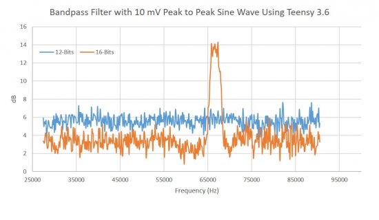
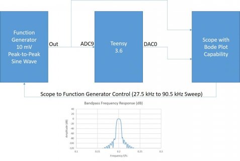
With regard to selecting 12-bit versus 16-bit, it does matter. The chart below is a bode plot of an 801-point finite impulse response bandpass filter I have running in real time on a Teensy 3.6. The filter program acquires the data using the ADC and outputs the result to the DAC. (The ADC and the DAC use DMA buffering.) The data acquisition rate of both the ADC and the DAC is set at 333 kHz. The frequency is swept from from 27.5 kHz to 90.5 kHz. The only difference between the two data sets is the ADC resolution. As you can see, there is a clear difference in both sensitivity and noise performance.
Attachments
Theremingenieur
Senior Member+
That‘s interesting and at the same time contradictory to the official data sheet and documentation. I wonder from where this difference does come.
That‘s interesting and at the same time contradictory to the official data sheet and documentation. I wonder from where this difference does come.
I didn't get the test setup exactly yet.
willie.from.texas
Well-known member
Theremingenieur
Senior Member+
I knew that there was a 16bit mode. But seen that the data sheet K66P144M180SF5V2.pdf says on page 47 that the ENOB in single ended 16bit mode is "only" 12.2 to 13.9 bits with 32x averaging, and still worse 11.4 to 13.1 bits with 4 x averaging, and finally they even don't dare giving a value without averaging, I didn't think that there would be a noticeable difference compared to 12bit mode. Driving the ADC with only a 10mVpp signal doesn't make things better, since the "good" upper 6 bits would never be used if you don't configure the PGA for x64...
willie.from.texas
Well-known member
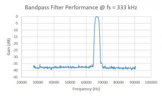
When I first got this filter working I was really surprised that I wasn't getting better performance. You can see from my filter design in the setup diagram that I should expect greater than -80 dB attenuation in the bandstop regions (in a perfect world). Then I read the performance spec... Although I'm convinced that I'm not getting 16-bit accuracy using 16-bit resolution, I'm clearly getting better performance than I would if I were only using 12 bits. Using 12-bits does buy you more acquisition bandwidth but since I am already using about 60% of the computational bandwidth running the filter at 333 kHz, I really can't go much faster so I figured may as well take advantage of the higher bit resolution. Besides, using the ADC in 12-bit mode does not mean your ENOB is 12-bits. I don't normally run the ADC with only 10 mVpp but did it in this case to illustrate the difference in sensitivity. In the 10 mVpp case my filter detected the signal at 16-bits but didn't at 12-bits. Below is the best performance I have been able to obtain with the Teensy 3.6.
W
W
Attachments
- Status
- Not open for further replies.