Teensy 4? testing mbed NXP MXRT1050-EVKB (600 Mhz M7)

Both of those files seem to say the RTC oscillator should need smaller capacitors, though neither document seem to be very specific about the crystal specs.

Test results I'm seeing here seem to show nearly ideal frequency 12 pF on the 24 MHz crystal and 20 pF on the 32 kHz crystal.

I just swapped out the 13 pF capacitors from the worst performing RTC, which had +58 ppm error in the first 4 min after powerup. With 20 pF caps (and some rosin-based flux still on the board) I'm now seeing about +4.5 ppm error. Going to let this one run an hour or so to check after warmup, but it's already slowed by about 0.5 ppm while writing this message.
 
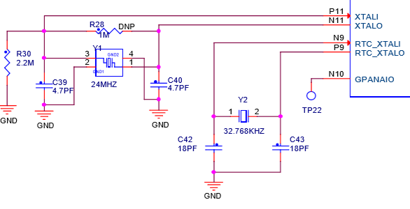
My curiosity always gets to me, so I took a look at what the EVKB had for crystals. So just as a reference the 2 crystals that the board uses are:
Code:
Y1	24MHZ	XTAL 24MHZ -- 30PPM 3.2X2.5MM SMD		TXC CORP	              7V24000002	xtlosc4_3p2x2p5mm_sm
Y2	32.768KHZ	XTAL 32.768KHZ 7PF 20PPM -- SMT		EPSON ELECTRONICS	FC-135 32.7680KA-AG3	XTAL2-3p2x1p5-SM
From the schematic it looks like they are using 18pf on the 32.768KHZ crystal and 4.7pf on the 24? Not 100% sure I am reading the schematic right or its the equivalent on the new boards, so here is the offending piece:
Capture.PNG

EDIT: Just looked at the datasheet for the 32mhz crystal and looks like based on the PN and datasheet there is a internal load cap of 7pf. Looks like there may be a 8pf load in the 24mhz as well.
 
Last edited:
With less precision, one could free-run the GPTx on the 32khz clock source, and read the GPTx counter on each GPS PPS interrupt.

FWIW
I configured the GPT timer to clock from the 32khz crystal and used the GPS PPS for a pin interrupt. In the ISR i read the GPTx counter and calculated cumulative ppm. I got -52 ppm for the eval board 32khz crystal. My earlier SDK RTC drift test against the core clock (24mhz) got -46 ppm, but the core clock had a drift of -6 ppm (-46 + -6 = -52 ppm ... all is good).
Code:
     crystal drift (ppm)
          EVK  EVKB   specs
24MHz     -14    -6    30
32KHz     -54   -52    20
 
Last edited:
I saw your comment in Teensy 4 (WIP) startup.c about 1050 SysTick clocking at 100khz. I did find one NXP thread confirming (but not explaining) that.
https://community.nxp.com/thread/482468

The SDK mbedtls and wolfssl benchmarks both use systick to time the benchmarks and config with
SysTick_Config(CLOCK_GetCoreSysClkFreq() / 1000U);
SysTick CTRL is configured for processor clock.
systick ctrl 10007 load 599999 val 59302 59300
So the SDK doesn't try to use the "external clock".

I configured SysTick on the eval board to use the "external clock" and confirmed it's running at 100khz.

I have been doing my eval board timings with free-running GPT timer at 1mhz.
 
Last edited:
Teensy 4 (WIP) observations:

In startup.c
Code:
// the external clock is really 100 kHz.  We use this clock rather than the
// ARM clock, to allow SysTick to maintain correct timing even when we change
// the ARM clock to run at different speeds.
Running SysTick at 100khz reduces the precision of micros() (delay.c) to 10 us. :(

Makefile is still using fpu for T3.6/T3.5 (-mfpu=fpv4-sp-d16 -fsingle-precision-constant), some gcc options for eval board SDK gcc
-fomit-frame-pointer -mcpu=cortex-m7 -mthumb -mfpu=fpv5-d16 -mfloat-abi=softfp
 
Oh, opps, the makefile is old. I do have -mfpu=fpv5-d16 in boards.txt. Haven't done any significant testing on float vs double.

The ARM toolchain in all prior versions of Teensyduino has numerous unused copies of the C library deleted. That saves dozens of megabytes on the download size. Turned out fpv5-d16 was one of those. Just a couple days ago I updated the toolchain part of Teensyduino's build for all 6 platforms.
 
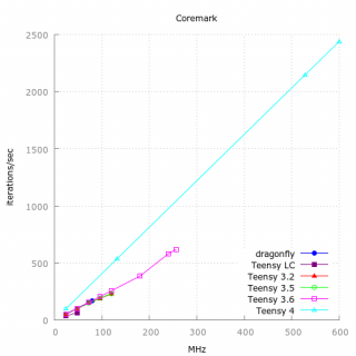
coremarkish update:

iterations/second from coremark on eval board at various CPU speeds (gcc v7.3 -O3)
Code:
    M7@600mhz      2438  
      @528mhz      2146
      @132mhz       536
       @24mhz        97
About 4 iterations/MHz.
corermark4.png

Other Teensy plots and more performance comparisons
 
Last edited:
This is probably way too early to ask this question but I tend to think ahead a little. I have been looking at the encoder sdk driver and it looks like it can easily be ported over to the teensy except it will require a xbar driver/setup. The question I have is there a protocol to port it over or should it be done from scratch?
 
Started experimenting with overclocking... mainly so I can test how different inductors are affecting the power supply.

Looks like I can overclock to 864 MHz with 1.4V. That's 0.1V over the 1.3V "absolute max" specified in the datasheet! The chip gets hot, but not burnt finger hot. Going to risk going all the way up to 1.575 soon, at least on 1 board.

Will commit the clock set code later today.

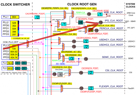
@Manitou - Have you see any info or examples on how to safely change IPG_PODF while the system is running? The ref manual shows a clock gate on the huge clock tree diagram, but I can't find any other documentation on it. Right now I'm just writing to IPG_PODF and hoping nothing breaks....

ipg_podf_gate.png
 
More "testing"... can't quite hit 1 GHz. Runs, but Coremark detects CRC errors. Fastest I can get to pass the test is 984 MHz, using 1.575 volts. Coremark is 3802, with gcc -02. The chip gets *really* hot.
 
More "testing"... can't quite hit 1 GHz. Runs, but Coremark detects CRC errors. Fastest I can get to pass the test is 984 MHz, using 1.575 volts. Coremark is 3802, with gcc -02. The chip gets *really* hot.

So much for … speed is secondary during the Beta :)

Yikes 1.3V MAX … pushed to 1.4V … 1.575V … and 984 MHz on a 600 MHz part … hopefully the supply is testing well [and the first beta boards will be good enough?] … that will leave the FLASH access in the dust - that extra RAM will be extra critical. Is there a nice heat sync that will fit and take out some of that extra heat ? Higher voltage will eat more than "specs say the MCU should consume 0.11ma/MHz. " right?
 
@Manitou - Have you see any info or examples on how to safely change IPG_PODF while the system is running? The ref manual shows a clock gate on the huge clock tree diagram, but I can't find any other documentation on it. Right now I'm just writing to IPG_PODF and hoping nothing breaks....

The M7 clock stuff is way above my pay grade -- the clock tree is intimidating. The NXP SDK (MCUXpresso IDE) has a clock configuration tool, but i have had no success with it. I've only run the NXP SDK example power_mode_switch. That example alters the clocks at run time, but it is lots of lines of C code (lpm.c). I couldn't even figure out how to get to your test setting of 396 mhz. So not only can i not write clock-altering code, I can't totally decipher the clock code others have written ...

Also, there is chapter in reference manual (ch 53) on temperature monitoring ... i haven't tried it, though a thread suggests there is an SDK example
https://community.nxp.com/thread/491004
 
Last edited:
@manitou -You made me look :) The tempmonitor is in the new v2.5.0 of the sdk - just downloaded it and tried it. The example sketch gets the initial temp and it shows how to throttle back the clock based on overtempt and then reset it when it cools down. Just have to figure out what the demo limits are.

If you just want the project I can just send it too you.
 
Indeed the clock tree is intimidating. Until recently I've mostly avoided it and just used the chip in the default config from startup, which is 396 MHz if you haven't burned any fuses.

My copy of SDK 2.5.0 doesn't have a power_mode_switch example or any file named lpm.c. Any chance you could send me that file, or just post a copy here? I'm not going to actually compile & run it, just look at their approach.

Here's what I've done so far. This is only from the ref manual and lots of experimenting. It's also quite long, and I'm still not doing stuff like turning off the PLLs for running at very slow speeds.

https://github.com/PaulStoffregen/cores/blob/master/teensy4/clockspeed.c

Even though this is really complex internally, my hope is we can offer Arduino users just 1 simple function that takes any integer for the clock speed and automatically takes care of all the clock tree complexity.
 
The chip is 10 mm square, so any bigger is adding cooling surface but not more area for heat transfer. I kept all the nearby parts shorter (the inductor is close) so you can use a bigger heatsink. Only the pushbutton and USB connector are taller, and they're about 4 mm away from the chip. On the 1st betas (which I hope to start shipping later this week), the space is wide enough for up to !18 mm to fit. On the final board, more than 13 mm will overhang the pins and likely short circuit them. So I'd look for heatsinks in the 10-12 mm range.

If you keep the voltage under 1.3V (the "absolute max" spec), a heatsink probably isn't needed anyway. The chip gets quite warm, but not really hot like if you run at 1.575V and push to 900+ MHz. So far I've only run 1 board that way, and only for a few minutes. I really have no idea how long you could expect your board to last if running it that far beyond the absolute max voltage.
 
Back
Top