Teensy 3.2 NVIC_ENABLE_IRQ not setting transmit interrupts

Status
Not open for further replies.

bmd1103

Member
I'm testing a routine to transmit a string of characters using standard 2400_8N2 serial format on UART0, then immediately convert the Tx pin to receive a PWM response. As part of this I want to use the TC interrupt to indicate that the stop bits for the last character have been sent.
Code:
#define IRQ_PRIORITY  64  // 0 = highest priority, 255 = lowest

byte message[2][6] = {  { 0xFF, 0xFE, 0xFE, 0xFE, 0xFE, 0x00 }, 
                        { 0xFF, 0xFE, 0xFE, 0xFE, 0xFE, 0x00 }  };
int phase, modID, i;
volatile boolean uartFlag;

void setup()
{
  Serial.begin(115200);
  Serial.println("Teensy_interrupt_Test_V3_1115a");Serial.println(" ++++++++++++++++++++++++ ");
  uart0Setup();
  Serial.print(UART0_C1, HEX);Serial.print("  ");Serial.print(UART0_C2, HEX);Serial.print("  ");Serial.print(UART0_C3, HEX);Serial.print("  ");Serial.print(UART0_C4, HEX);Serial.print("  ");Serial.println(UART0_C5, HEX);
  Serial.print(UART0_S1, HEX);Serial.print("  ");Serial.println(UART0_S2, HEX);Serial.println(SIM_SCGC5, HEX);Serial.println("  *****************************  ");

  for (int i = 3; i < 13; i++)
  {
    pinMode(i, OUTPUT);
    digitalWrite(i, LOW);
  }
  modID = 0;
  i = 0;
}    // </setup()>

void loop()
{
  message[0][5] = cmdCheckSum(message[0]) | modID;
  message[1][5] = cmdCheckSum(message[1]) | modID;

  for (int i = 0; i < 6; i++)
  {
    UART0_D = message[0][i];
  }
  modID++;
  if (modID > 3) modID = 0;
  delay(40);
}     // </loop()>

void uart0Setup()
{
  SIM_SCGC4 |= SIM_SCGC4_UART0;   //Turn on clock to UART0
  PORTB_PCR17 = 0x300;     // Alt 3 for PTB17(pin 1) to be UART0 output

  UART0_BDH = 0x07;       // 2400 bd @ 72 MHz
  UART0_BDL = 0x53;
  UART0_C2 = 0x00;        // Clear to allow FIFO setup
  UART0_PFIFO = 0xA0;     // Enable 8-bit FIFO 
  UART0_CFIFO = 0x80;     // Flush FIFO
  UART0_C1 = 0x10;        // M = 1 for 9 bits (2nd stop bit  = bit 9)
  UART0_C2 |= (UART_C2_TIE | UART_C2_TCIE | UART_C2_TE);      // Enable tx interrupts and tx function
  Serial.print(" -- ");Serial.println(UART0_C2, HEX);
  UART0_C3 = 0x40;        // T8 set for 2nd stop bit
  NVIC_SET_PRIORITY(IRQ_UART0_STATUS, IRQ_PRIORITY);
  NVIC_ENABLE_IRQ(IRQ_UART0_STATUS);
  Serial.print(" -- ");Serial.println(UART0_C2, HEX);
}     // </uart0Setup()>

void uart0_ISR()
{
  if ((UART0_C2 & UART_C2_TCIE) && (UART0_S1 & UART_S1_TC))
  {
    uartFlag = true;
  }
}     // </uart0_ISR()>

byte cmdCheckSum(byte data[])
{
  //  int dataLength = sizeof(data);
  int CS = 0;
  for (int i = 1; i < 5; i++)
  {
    CS = CS + data[i];
  }
  CS = CS + (CS >> 8);
  CS = CS + (CS << 4);
  CS = CS & 0xF0;
  return CS;
}

Even though I am explicitly setting the TCIE and TIE bits in UART0_C2, the NVIC_ENABLE_IRQ(IRQ_UART0_STATUS) function is clearing these and setting the RIE, RLIE, and RE bits, changing the register from 0xC8 to 0x3C..
Code:
Teensy_interrupt_Test_V3_1115a
 ++++++++++++++++++++++++ 
 -- C8
 -- 3C
10  3C  40  0  0
C0  0
43F82
  *****************************

My understanding is that NVIC_ENABLE_IRQ should simply activate the associated vector without affecting any of the associated register bits - this is obviously incorrect. If someone can enlighten me as to what is happening, I'd be grateful.
 
It's a macro:

Code:
#define NVIC_ENABLE_IRQ(n)    (*((volatile uint32_t *)0xE000E100 + ((n) >> 5)) = (1 << ((n) & 31)))

You see, it updates adresses 0xE000E100 + (n) >> 5) only (and - correct - acivates the vectors only)
It does not know anything about UARTs and does not touch them.
 
That's what I thought. So why does the value of UART0_C2 not remain as set? Since my original post, I've tried setting it after the NVIC_ENABLE_IRQ line and still get the same result - 0x3C as opposed to 0xC8.
 
I've done a lot more playing with this and think I've sorted the original problem. I now need advice on the correct procedure to use tailor-made interrupt functions with the Teensy. I think what was happening with the original issue was that I had the UART0_S1_TC bit set when I activated the interrupts, so the routine was executing the interrupt immediately. I've modified the program to avoid this.

From further reading, I understand that the correct procedure is to simply assign the interrupt handler the name given in mk20dx128.c for the Teensy 3.2 - in my case, uart0_status_isr(void). I have done this:
Code:
#define IRQ_PRIORITY 64

boolean uartFlag;
void setup() 
{
  Serial.begin(115200);
  Serial.println(" Teensy3.2_uart_int_tests_1811a");Serial.println(" ++++++++++++++++++++++++ ");

  uart0Setup();
  attachInterruptVector(IRQ_UART0_STATUS, uart0_status_isr);
  Serial.print(" S1 = ");Serial.println(UART0_S1, HEX);
  uint8_t a = UART0_C2;
  UART0_C2 = (UART_C2_TIE | UART_C2_TCIE | UART_C2_TE);      // Enable tx interrupts and tx function
  uint8_t b = UART0_C2;
  UART0_C2 = 0xC8;      // Enable tx interrupts and tx function
  uint8_t c = UART0_C2;
  uint8_t d = UART0_C2;
  Serial.print(" a = ");Serial.println(a, HEX);
  Serial.print(" b = ");Serial.println(b, HEX);
  Serial.print(" c = ");Serial.println(c, HEX);
  Serial.print(" d = ");Serial.println(d, HEX);
  Serial.print(" e = ");Serial.println(UART0_C2, HEX);
  Serial.print(" flag = ");Serial.println(uartFlag);
}    // </setup()>

void loop()
{
}

void uart0Setup()
{
  SIM_SCGC4 |= SIM_SCGC4_UART0;   //Turn on clock to UART0
  NVIC_SET_PRIORITY(IRQ_UART0_STATUS, IRQ_PRIORITY);
  NVIC_ENABLE_IRQ(IRQ_UART0_STATUS);
  PORTB_PCR17 = 0x300;     // Alt 3 for PTB17(pin 1) to be UART0 output

  UART0_BDH = 0x07;       // 2400 bd @ 72 MHz
  UART0_BDL = 0x53;
  UART0_C2 = 0x00;        // Clear to allow FIFO setup
  UART0_PFIFO = 0xA0;     // Enable 8-bit FIFO 
  UART0_CFIFO = 0x80;     // Flush FIFO
  UART0_C1 = 0x10;        // M = 1 for 9 bits (2nd stop bit  = bit 9)
  UART0_C2 = (UART_C2_TE);      // Enable tx function
  UART0_C3 = 0x40;        // T8 set for 2nd stop bit
//  Serial.print(" ++ ");Serial.println(UART0_C2, HEX);
//  UART0_C2 = 0xC8;      // Enable tx interrupts and tx function
//  Serial.print(" ** ");Serial.println(UART0_C2, HEX);
  
}     // </uart0Setup()>

void uart0_status_isr(void)
{
//  if ((UART0_C2 & UART_C2_TCIE) && (UART0_S1 & UART_S1_TC))
//  {
    uartFlag = true;
//  }
}     // </uart0_ISR()>
but when compiling I get:
Code:
Build options changed, rebuilding all
C:\Users\bmdur\AppData\Local\Temp\arduino_build_290251/..\arduino_cache_230823\core\core_teensy_avr_teensy31_usb_serial,speed_72,opt_o2std,keys_en-us_4939f5412a75a8560acb0f9e98268f02.a(serial1.c.o): In function `uart0_status_isr':

C:\Program Files (x86)\Arduino\hardware\teensy\avr\cores\teensy3/serial1.c:508: multiple definition of `uart0_status_isr'

C:\Users\bmdur\AppData\Local\Temp\arduino_build_290251\sketch\Teensy3.2_uart_int_tests_1811a.ino.cpp.o:D:\Software development\Arduino\Sketches\Teensy3.2_uart_int_tests_1811a/Teensy3.2_uart_int_tests_1811a.ino:55: first defined here

c:/program files (x86)/arduino/hardware/tools/arm/bin/../lib/gcc/arm-none-eabi/5.4.1/../../../../arm-none-eabi/bin/ld.exe: Disabling relaxation: it will not work with multiple definitions

collect2.exe: error: ld returned 1 exit status

Error compiling for board Teensy 3.2 / 3.1.

This result is the same both with and without the attachInterruptVector() line in the code.

Again, any advice on the correct procedure to call an interrupt handler of my choice would be gratefully received.
 
That is a 'weak' function so it can be redefined. But it is referenced in a 'c' file and your replacement is in a .INO (cpp) file?

It may need to be wrapped something like this to avoid name mangling conflict if I'm glancing at this right:
Code:
#ifdef __cplusplus
extern "C" {
#endif
void uart0_status_isr(void)
{
    uartFlag = true;
}     // </uart0_ISR()>
#ifdef __cplusplus
} // extern "C"
#endif

<edit>opps: weak in interrupt table - but defined already in Serial1.c - like the console error says
 
Last edited:
@Frank _B -
If I change my interrupt routine, it brings me back to my original problem - and I don't hit the interrupt handler.
Code:
#define IRQ_PRIORITY 64

boolean uartFlag;
void setup() 
{
  Serial.begin(115200);
  Serial.println(" Teensy3.2_uart_int_tests_1811a");Serial.println(" ++++++++++++++++++++++++ ");

  uart0Setup();
//  attachInterruptVector(IRQ_UART0_STATUS, uart0_status_hdlr);
  Serial.print(" S1 = 0x");Serial.println(UART0_S1, HEX);
  uint8_t a = UART0_C2;
  UART0_C2 = (UART_C2_TIE | UART_C2_TCIE | UART_C2_TE);      // Enable tx interrupts and tx function
  uint8_t b = UART0_C2;
  UART0_C2 = 0xC8;      // Enable tx interrupts and tx function
  uint8_t c = UART0_C2;
  uint8_t d = UART0_C2;
  Serial.print(" a = 0x");Serial.println(a, HEX);
  Serial.print(" b = 0x");Serial.println(b, HEX);
  Serial.print(" c = 0x");Serial.println(c, HEX);
  Serial.print(" d = 0x");Serial.println(d, HEX);
  Serial.print(" e = 0x");Serial.println(UART0_C2, HEX);
  Serial.print(" flag = ");Serial.println(uartFlag);
}    // </setup()>

void loop()
{
}

void uart0Setup()
{
  SIM_SCGC4 |= SIM_SCGC4_UART0;   //Turn on clock to UART0
  NVIC_SET_PRIORITY(IRQ_UART0_STATUS, IRQ_PRIORITY);
  NVIC_ENABLE_IRQ(IRQ_UART0_STATUS);
  PORTB_PCR17 = 0x300;     // Alt 3 for PTB17(pin 1) to be UART0 output

  UART0_BDH = 0x07;       // 2400 bd @ 72 MHz
  UART0_BDL = 0x53;
  UART0_C2 = 0x00;        // Clear to allow FIFO setup
  UART0_PFIFO = 0xA0;     // Enable 8-bit FIFO 
  UART0_CFIFO = 0x80;     // Flush FIFO
  UART0_C1 = 0x10;        // M = 1 for 9 bits (2nd stop bit  = bit 9)
  UART0_C2 = (UART_C2_TE);      // Enable tx function
  UART0_C3 = 0x40;        // T8 set for 2nd stop bit
//  Serial.print(" ++ ");Serial.println(UART0_C2, HEX);
//  UART0_C2 = 0xC8;      // Enable tx interrupts and tx function
//  Serial.print(" ** ");Serial.println(UART0_C2, HEX);
  
}     // </uart0Setup()>

void uart0_status_hdlr(void)
{
//  if ((UART0_C2 & UART_C2_TCIE) && (UART0_S1 & UART_S1_TC))
//  {
    uartFlag = true;
//  }
}     // </uart0_ISR()>

gives as output:
Code:
 Teensy3.2_uart_int_tests_1811a
 ++++++++++++++++++++++++ 
 S1 = 0xC0
 a = 0x8
 b = 0xC8
 c = 0xC8
 d = 0x3C
 e = 0x3C
 flag = 0
So when starting the interrupt flags in S1 are both set, as expected. My uart0Setup only enables the transmit function - it does not enable any interrupts (result a). Explicitly setting the interrupts ddoes enable them, and I would expect the interrupt routine to be executed at that stage. This should set uartFlag.
The results b, c, and d are for consecutive reads of UART0_C2. There are no writes to UART0_C2 between the assignment functions for c and d, yet the value has changed.

It appears to me that the interrupt is being called, but not the one I've written. Any ideas as to other lines of investigation?
 
Maybe, but this is not a problem with the vector.
Try this:
Code:
//original vector
void (*prevInterruptPtr)(void);

void uart0_status_hdlr(void) {
 digitalWriteFast(13, !digitalReadFast(13)); 
 
 //Just for fun, call original vector now :-) - This is called interrupt chaining. You don't need it, but its fun...:)
 prevInterruptPtr();
}

void setup() {
 pinMode(13, OUTPUT); 
 prevInterruptPtr = _VectorsRam[IRQ_UART0_STATUS + 16];
 Serial1.begin(9600);

 attachInterruptVector(IRQ_UART0_STATUS, uart0_status_hdlr); 
}

void loop() {
  Serial1.print("x");  
  delay(100);
  }

You see, it works. With any vector.

Edit: for your problem, i'd take a close look what the original vector does, and copy that. You know where the sourcecode is?
 
... to transmit a string of characters using standard 2400_8N2 serial format on UART0, then immediately convert the Tx pin to receive a PWM response.

Why go to all this trouble to craft your own ISR when the supplied code provides Serial1.flush() and Serial1.end() ?
 
My guess is you're going to answer that you may believe the supplied Serial1 code isn't good enough for your project's tight timing requirements? If that's really your motivation, I'd like to ask whether you've actually tested it?

I ran a quick test just now, with this very simple program.

Code:
void setup() {
  pinMode(4, OUTPUT);
}

void loop() {
  Serial1.begin(2400, SERIAL_8N2);
  Serial1.print("Hello World");
  Serial1.flush();
  Serial1.end();
  digitalWriteFast(4, HIGH);
  delay(1);
  digitalWriteFast(4, LOW);
  delay(100);
}

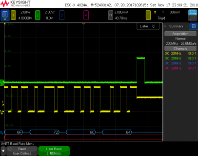
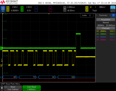
I connected two 10K resistors to the TX1 signal (digital pin 1), so when the TX1 transmitter shuts off the signal will "float" to a distinct voltage that isn't logic low or logic high. This code also creates a pulse after Serial1.end() finishes, so we can see how quickly your PWM measuring code might be able to run. Here's how the waveforms look my oscilloscope.

file.png

As another quick test, I changed SERIAL_8N2 to SERIAL_8N1, so it only transmits 1 stop bit. Here's the result.

file.png

It's pretty clear to see the speed of turning off the serial port and running other code is so much faster than 1 stop bit time, at least at this fairly slow baud rate. So much trouble to mess with custom interrupts hardly seems worthwhile.


Then again, if your answer is you simply love playing with interrupts and hardware registers, of course keep going. But if you just want to get your project working, maybe try using the existing Serial1 functions. They work very well.
 
Paul - before I reply I'd like to express my appreciation for the time and effort you put in to the Teensy system.

As someone who has been working with computers for over 50 years, one of my motives for working on things like this is to come to grips with the "hows" and "why"s of what is done - as well as making good use of the results in one way or another. Hence my desire to understand just how 2 consecutive reads of a single register can produce different results.

My current project could involve up to 4 or 5 serial channels, all using the same protocol, and I am attempting to forestall possible problems, both with the control of that many uarts all at once and with the pin interrupts and FTMs that I'll be introducing later. I have successfully used the standard Serial1 routines. I'll try chaining the interrupts to see what happens.

Thanks for your time and support.
 
Err.. no!! The chain was an example only. This way i did'nt have to bother with the internals of that interrupt, it was a shortcut - I wrote that code in 3 minutes.
It should show, that your vector gets called correctly if you use attachInterruptVector() (edit: you suspected problems).
bmd1103 said:
It appears to me that the interrupt is being called, but not the one I've written. Any ideas as to other lines of investigation?
The example blinks the LED.
Best is, to look at the the existing code and learn how it handles the registers.

But Paul is right. Keep it simple!

Sorry if my my post was not clear - My English is not good.
 
Last edited:
@Frank_B - it worked and made sense to me. The new _isr() was indeed called and the LED flashed - and with the chain call to the old _isr() with "prevInterruptPtr();" it worked.
 
I have looked at the existing code and seen how it handles the registers. Because I'm dealing with messages that are only 6 bytes long, and am not using the read side of the serial port, I have no need for the circular buffers (at least with Serial1). I want to dump 6 bytes into the FIFO, do a lot of other stuff while the message is being processed, and come back to the communications when the TC flag is set. For this to work without polling, I'd have to initiate the read code within the serial interrupt handler. I'd like to try initiating the pin interrupts within the UART handler, then turn the serial transmitter off until the receive transaction is complete.
 
Thank you Defragster.

Well, I would it do this way (If I really wanted to play with it):

1) copy the code
2) remove the unneeded stuff
- now you have the essential code that deals with the registers, and you can learn how they are used -
3) add your code
 
Agreed, just copying the existing code would save a lot of time. This could probably be done the desired way by just adding 1 callback from the ISR for the transmit complete. I suppose the overhead of first copying the data to the buffer before putting it all into the FIFO could also be eliminated. Whether that's worthwhile, for only 6 bytes that take 25 ms to transmit is questionable.
 
I guess one of the things I need to come to grips with is that with the Teensy 3.2 etc there isn't quite the need to conserve memory and cycle time as there is with the chips I've been working with!
 
Yes, it is.
About speed: For the T3.6 there is a C64 emulator - it emulates _all_ the hardware - and handles its interfaces (e.g. Serial IEC and a UART) with bitbanging in the software......... partly in the emulated 6502 assembler (c64-rom routines).....

The teensy are underestimated by many people.
 
Status
Not open for further replies.
Back
Top