Function generator using teensy

Status
Not open for further replies.

paul_H

Member
Hello people
I am wondering if we can create a function generator with high frequency up to 30MHz using teensy and a AD99833 which is a low power, programmable waveform generator capable of producing sine, triangular, and square wave outputs. You can read more from this link:
https://www.analog.com/en/products/ad9833.html#product-overview

And is there any good resources for such projects that can help me?

Thanks in advance
 
Looking at the data sheet, the AD9833 has a maximum output frequency of 12.5 and not 30MHz, but that's already not bad. It communicates over high speed SPI, so everything can achieved using the corresponding standard library. Things might become easier if one packs the higher level functions into a new library which then would call the SPI library. There are just 5 registers to write, one control, two frequency and two phase registers which looks rather easy to achieve with a few functions, packing the desired data accordingly.

This data sheet contains all the needed programming information.
 
THANKS Theremingenieur AND PaulS
I tried to write my own code but it is look like there was something wrong
my code is:
Code:
#include <SPI.h>
const byte FSYNC = 10;
 

void setup() {
  Serial.begin(9600);
  
 }
void AD9833setup() {
  pinMode(FSYNC, OUTPUT);
  digitalWrite(FSYNC, HIGH);

  SPI.begin();
  delay(50); 
 
}
void WriteRegister(int dat) { 
  SPI.setDataMode(SPI_MODE2);       
  
  digitalWrite(FSYNC, LOW);           // Set FSYNC low before writing to AD9833 registers
  delayMicroseconds(10);              // Give AD9833 time to get ready to receive data.
  
  SPI.transfer(dat>>8);               // Each AD9833 register is 32 bits wide and each 16
  SPI.transfer(dat&0xFF);             // bits has to be transferred as 2 x 8-bit bytes.

  digitalWrite(FSYNC, HIGH);          //Write done. Set FSYNC high

}
void AD9833reset() {
  WriteRegister(0x100);   // Write '1' to AD9833 Control register bit D8.
  delay(10);
}

void AD9833setFrequency(long frequency, int Waveform) {


  long FreqWord = (frequency * pow(2, 28)) / 25.0E6;
  
  int MSB = (int)((FreqWord & 0xFFFC000) >> 14);    //Only lower 14 bits are used for data
  int LSB = (int)(FreqWord & 0x3FFF);
  
  //Set control bits 15 ande 14 to 0 and 1, respectively, for frequency register 0
  LSB |= 0x4000;
  MSB |= 0x4000; 
  
  WriteRegister(0x2100);          //DB13 is set to 1. This allows a complete word to be loaded
                                  //into a frequency register in two consecutive writes. The
                                  //first write contains 14 LSBs. The second write contains 14 MSBs. 
                                  //RESET bit DB8 is set to 1          
                                  //This resets internal registers to 0, which corresponds to an analog output of midscale

  WriteRegister(LSB);                  // Write lower 16 bits to AD9833 registers
  WriteRegister(MSB);                  // Write upper 16 bits to AD9833 registers.
  WriteRegister(0xC000);               // Phase register
  WriteRegister(Waveform);             // Exit & Reset to SINE, SQUARE or TRIANGLE
}
void loop() {
  int Waveform;
  
 AD9833reset();
// AD9833 documentation advises a 'Reset' on first applying power.

AD9833setup();
// Set the frequency and waveform registers in the AD9833.
AD9833setFrequency( 10000, 0x2020); //  WAVE_SINE = 0x2000,
                                  // WAVE_SQUARE-MSB = 0x2028,
                                  // WAVE_SQUARE-MSB/2 =0x2020,
                                  // WAVE_TRIANGLE = 0x2002.

//Serial.println(AD9833setFrequency( 0x400, 0x2000));
                                 
}

my connections were:
FSYNC with pin 10
Sclck with pin 13
SData with pin 11
Vcc with 3.3V pin
GND with GND
OUT with CH2 Oscilloscop (+ve)
REF with CH2 Oscilloscop (-ve)

I used a module, you can take a look here:
https://www.amazon.com/GAOHOU-CJMCU-9833-AD9833-Generator-Monitor/dp/B07DLMWC3K

can anyone help me to know what the mistake i made?

regards :)
 
Hi Paul,

Here is the basic code to generate a 1000Hz sine wave:
Code:
#include <SPI.h>                      // pin 13 (SCK), pin 11 (MOSI), AD9833 generator
const int FSYNC = 10;                 // pin 10 (SS)
#define SPI_CLOCK_SPEED 12000000      // 12MHz SPI clock
unsigned long MCLK = 25000000;        // AD9833 onboard crystal reference frequency
unsigned long freq = 1000;            // set initial frequency

void setup() {
  pinMode (FSYNC, OUTPUT);
  digitalWrite(FSYNC, HIGH); 
  SPI.begin();
  AD9833setFrequency(freq);           // set frequency
}

void loop() {
}

void AD9833setFrequency(long frequency) {
  long FreqReg = (frequency * pow(2, 28)) / MCLK;
  int MSB = (int)((FreqReg & 0xFFFC000) >> 14);    // only lower 14 bits are used for data
  int LSB = (int)(FreqReg & 0x3FFF);

  LSB |= 0x4000;                      // DB 15=0, DB14=1
  MSB |= 0x4000;                      // DB 15=0, DB14=1

  WriteRegister(0x2100);              // put AD9833 into reset and tell it to accept 14bit words (DB13=1, DB8=1)
  WriteRegister(LSB);                 // write lower 16 bits to AD9833 registers
  WriteRegister(MSB);                 // write upper 16 bits to AD9833 registers
  WriteRegister(0xC000);              // write phase register
  WriteRegister(0x2000);              // take AD9833 out of reset and output sinewave (DB8=0)
}

void WriteRegister(int data) {
  SPI.beginTransaction(SPISettings(SPI_CLOCK_SPEED, MSBFIRST, SPI_MODE2));
  digitalWrite(FSYNC, LOW);           // set FSYNC low before writing to AD9833 registers
  SPI.transfer16(data);
  digitalWrite(FSYNC, HIGH);          // write done, set FSYNC high
  SPI.endTransaction();
}

I just tried this and it works on my TeensyLC and the board I linked in my previous email.
You may want to use SPI transactions. And you can do 16bit SPI transfers: "SPI.transfer16(data)".
Also you don't need to a first reset (AD9833reset()) since that reset is part of WriteRegister(0x2100).

Regards,
Paul
 
big thanks for you PaulS
it works properly and I get good sinKsqr and triangle waves.
but I cannot get a signal more than 2MHz, which is unexpected i cannot find any logic reason for this! since AD9833 freq reach up to 12 MHz, do you have any idea about that?

Regards
 
Hi Paul,

That's interesting. In the above code I only modified one line to "unsigned long freq = 10000000; // set initial frequency", compiled it and ran it on a Teensy LC.
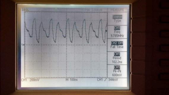
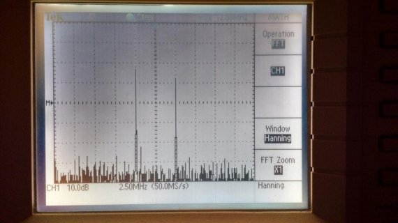
The oscilloscope correctly shows the 10Mhz signal and the intermodulation product of 15MHz [25MHz minus 10MHz].

IMG_20181125_225839928_HDR.jpg

Spectrum [FFT], one peak @ 10MHz and one @ 15MHz
IMG_20181125_225717984_HDR.jpg

Since 10MHz is very close to the Nyquist frequency [12.5MHz], you have to use a very, very sharp low-pass filter to suppress anything above the Nyquist frequency and thus get rid of the intermodulation frequency.

Anyway, you should see something similar to what I see on my scope.
Are you exactly using the code as shown in my previous message?
Can you share your code? And perhaps a photo of your setup?

Regards,
Paul
 
Since 10MHz is very close to the Nyquist frequency [12.5MHz], you have to use a very, very sharp low-pass filter to suppress anything above the Nyquist frequency and thus get rid of the intermodulation frequency.

Are you exactly using the code as shown in my previous message?

Hi PaulS
thanks for replying, yes it is logical to get an interrupted signal at 10MHz, but why I cannot get a good signal at 2,3,4,5 or 6MHz since its less than Nyquist freq! The following pic I get at 6MHz (oh I didnt find any option to post a photo! how do you post your photos?! any its look like the one you sent), even the amplitude its not constant with freq changing, its varying from about 450mV to 660 mV at (5-1000000)Hz!

do you have any suggestion?!

yes, I have used exactly the code you have shown
Regards
 
Hi Paul,

why I cannot get a good signal at 2,3,4,5 or 6MHz since its less than Nyquist freq

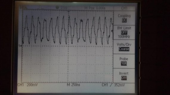
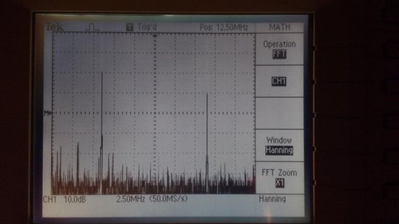
It's kind of fundamental: if you do not use a low-pass filter, you will always see the intermodulation frequency a.k.a. alias [sample frequency minus intended frequency, e.g. 25MHz - 6MHz] mixed up with the intended frequency [6MHz].
I guess you see this? 6MHz & 19MHz mixed
IMG_20181128_202049282.jpg

IMG_20181128_202012070.jpg
See https://en.wikipedia.org/wiki/Nyquist_frequencyhttps://en.wikipedia.org/wiki/Nyquist_frequency and https://en.wikipedia.org/wiki/Reconstruction_filter for more details.
Also google for "dac filter".

For attaching pictures in your post, use this button:
screen.png

Regards,
Paul
 
Status
Not open for further replies.
Back
Top