"SPI Repeater" for long APA102 strands?

Status
Not open for further replies.

bressler

Member
Hi Paul and forum members,

I am trying to make a pretty long string of APA102Cs - around 2,500 LEDs. I need it to run at 2.2 MHz at least to get the frame rate I need. As we know from Paul's post on the subject, the shortening of the clock duty cycle and the lengthening rise-time of the clock limit both the usable clock rate and the total length of strips of APA102 LEDs.

I have an idea: What about using a Teensy LC as an "SPI repeater" - it takes a (still barely usable) SPI in from the last LED on section of APA201s on SPI0, and immediately passes whatever it gets along to SPI1, which is in turn plugged into the next set of LEDs. This introduces an imperceptible latency while fully resynthesizing the SPI signal, restoring the clock duty cycle and waveshape. I imagine you could insert these guys in every 750 or 1000 LEDs or so and have very long overall strands. We get long APA102 strands. Paul sells more Teensy LCs. Everyone wins!

To do this, I'd need APA102Cs feeding SPI0 as an SPI Slave (I think), with the code reading bytes and immediately retransmitting them on SPI1. Would this be possible? My attempts thus far have not worked, but I'm pretty sure I'm not handling SS correctly. Has anyone tried this, or can anyone tell me whether it might work?

Thanks a ton. And for those who celebrate it, Happy Thanksgiving!

Best,
Bryan
 
you should run the SS line into an attachinterrupt on the slave, and not use SPI transactions on the slave when it connects to the strip. Whether this works or not (based on above) is beyond me, but worth a try. Also for the SPI transactions part, run it once only on slave to enable the SPI master clock frequency and mode to the slave and keep it always enabled, then hope that the input pin of the slave running attachinterrupt on FALLING EDGE is connected to the master’s CS pin to the slave. If you need help at implementing SPI slave support for teensy LC, you may check out my library SPI_MST, the source should guide you in the right direction, the rest you need to do is actually test to see if it works (SPI repeater) :)
 
Hi tontont81...thanks a ton for your post. One thing I'm not clear on reading your post is what I electrically connect the SS pin to. The last LED has no SS - just clock and data out. So when you say "then hope that the input pin of the slave running attachinterrupt on FALLING EDGE is connected to the master’s CS pin to the slave"...I'm not sure how to proceed since the master is the last LED and it has no CS output.

These LEDs may not technically be SPI - but rather "SPI-like." But I effectively need to sample the SPI0 data line on the rising edge of the SPI0 clock, then turn around and put the data bit on the SPI1 data line and emit an SPI1 clock pulse. Perhaps I should stop thinking of this in terms of SPI and start just thinking of it as a bit-banging operation with four digital pins - two in and two out, maybe with the clock-in pin on an interrupt.

What do you think?
 
Last edited:
if no one can help you figure it out in a reasonable time get a fleabay equivalent strip link as yours and ill order one to see what i can do :)
 
I’ll also mention on the LC, SPI1 in slave mode is faster than SPI0, so it will be better to use SPI1 as slave and SPI0 for the strip if you plan to use the LC.
 
As with all projects like this, it might actually help if you showed what you have actually tried and failed with. There might be some simple bug in it... Also show/describe wiring. Example is there a common ground?

I might be missing something, but if it were me and I was wanting to use the LC to only cleanup the signal, I might try a few experiments.

a) Can the LC actually drive the APA102Cs leds? Or do they need 5V? If they need/want +5v you might need some level shifter...

b) Assuming that you have the LC setup to drive these LEDs properly, do you need SPI or can you get away with something real simple like:
Code:
void setup() {
   pinMode(0, INPUT);
   pinMode(1, OUTPUT);
   pinMode(2, INPUT);
   pinMode(3, OUTPUT);
}
void loop() {
    for(;;) {
        digitalWrite(1, digitalRead(0));
        digitalWrite(3, digitalRead(2));
    }
}
That is simply echo the IO state from one pin to another? Of course if this works, wonder if then you could get away with just using some simple level shifter in the chain... Maybe something like: https://www.sparkfun.com/products/12009 or https://www.adafruit.com/product/757 Would need to verify they are fast enough...


c) Or do you need to do a little more filtering and fixing of the actual pulses... Could for example detect the pulses on the input pins, and then generate pulses on the output pins, with the desired pulse widths...

d) finally could go with SPI and SPI1, but you have all of the fun of SPI slave code and then driving the SPI output, and worry about timings and interactions...

Sounds like fun!
 
Thanks tonton81 and KurtE for your posts.

The more I thought about this last night, the more I was remembering bit-banging SPI back in the day, and it worked fine. So last night I came up with an idea to do this with straight digital I/O and eschewing SPI entirely - the LC's whole job in life is going to be to make a new signal for the next section of LEDs, it should be able to run fast with nothing else to do. And that idea is alot like the code KurtE posted - details below.

To answer KurtE's questions, yes, the LC (or any Teensy I've used) can directly drive the LEDs. It is really only driving the first LED - then the LEDs drive each other the rest of the way down the chain.

And as for things I tried - I tried using CMOS Schmitt triggers to reshape the clock and data, and that sorta worked, but part of the problem is that the clock signal duty cycle is getting smaller through each LED (that's part of what Paul described in his post), so fixing the rise of the clock signal isn't really enough. That's why I was thinking of this repeater - it rebuilds the clock signal with full duty cycle again.

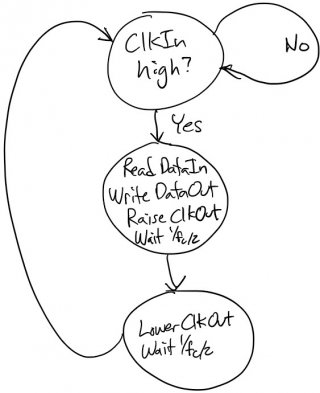
Last night I came up with this idea. Let us assume four digital lines:

ClkIn - clock signal from last LED in chain
DataIn - data signal from last LED in chain
ClockOut - clock signal we're sending to the next LED in the chain
DataOut - data signal we're sending to the next LED in the chain

And this little finite state machine:

SPIRepeaterFSM.jpg

This machine has to know the intended clock frequency, but in my case I do. This may well work, and I'm going to try to implement it tonight if I have time.

If this works it is much simpler than trying to actually use SPI. These LEDs aren't really SPI since they don't have CS/SS and are only one-way anyway.

Thoughts?

Thanks a ton!!
 
Last edited:
And in retrospect, that last state in the FSM says "wait 1 / fc / 2" - it probably shouldn't do that - it should just go back to the top state and leave ClkOut low until the next rise of ClkIn. Otherwise I'd risk missing a ClkIn rise.
 
Status
Not open for further replies.
Back
Top