Neopixels and EL paper

Status
Not open for further replies.

shadlx

Member
Hello

We have a project with a 9x12 grid of 5mm through hole neopixels mounted on custom PCBs going through holes cut in EL paper, when the EL paper is off they are fine, however as soon as the paper turns on they flash in a crazy fashion.

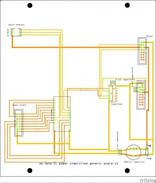
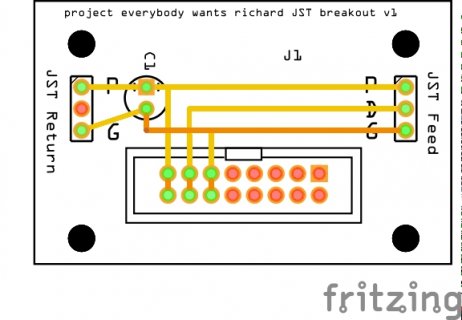
I've attached our PCB designs showing the main PCB which houses the teensy and network adaptor (stacked), the breakout from ribbon to JST connector and the PCB strips (of which we have 8, they are wired with the + and -ve joined at either end, and data snaking through.

Does anyone have any ideas as to what we could do to avoid this interference?

NB, code wise we get the issue with a simple sketch such as
Code:
#include <Adafruit_NeoPixel.h>
#define NEO_PIN            8
#define NUMPIXELS      108
Adafruit_NeoPixel pixels = Adafruit_NeoPixel(NUMPIXELS, NEO_PIN, NEO_GRB + NEO_KHZ800);

void setup()
{
  pixels.begin();
}
bool on=false;
void loop()
{
   for (int i=0; i<NUMPIXELS; i++)
   {
       pixels.setPixelColor(i, (on?0 : 100), 0, 0);
    }
    pixels.show();
    on = !on;
    delay(500);
}

Thanks!

Richard
simplified generic board v1_pcb.jpg
map long neopixel v2_pcb.jpg
JSTBoard_pcb.jpg
 
The most likely source of interference is the inverter driving the EL sheet, does is still interfere when the inverter is running but sheet is unpluged?

Fixing it will probably involve a mix of filtering the noise from the inverter and improving shielding for the pixels. Unclear from the drawing, is there any shared power involved between the inverter and the pixel 5V supply? It may be informative if still possible to operate the system with varying separations between the EL sheet, the EL inverter, the Teensy and the pixels to work out which part is impacting what. If you are lucky just increasing separation distances will fix it but suspecting the problem is the couple of mm between the the radiated RF from the EL sheet and the pixel data lines and that is pretty integral to your effect.

If trying to add filtering to the inverter be very careful given it will be producing a couple of hundred volts.
 
Hello, thanks for this - the EL paper has a separate (240v) PSU, we have tried various permutations of locations and cable routes but the only thing that seems guaranteed to cause the interference is putting the paper on the LEDs - we have made the holes 12mm (the LEDs are 5mm) to give a bit of space, but this doesn't really help.

I have been looking at whether there is any smoothing possible on the PSU for the EL paper but can't find any details - it seems to be 120v at 1200hz so I'm not sure what I could do that wouldn't blow the thing up!

Richard
 
Filtering the inverter would involve adding a resonant filter to tame the high frequency harmonics to keep them away from the 800khz the neopixels are operating at. Which is a non trivial challenge on a power system. Adding a ferrite bead https://en.wikipedia.org/wiki/Ferrite_bead may be a low complexity solution but will suck some of the power from the inverter as well as those higher frequencies.

Adding an earth plate between the sheet and the pixels may help - the problem is most likely not the pixels themselves but the wires between them picking up interference from the EL sheet which is acting as an antenna. So an Earthed sheet with a seperate ground may help even with holes for the pixels (though a valid test is to try it without holes first). What I'm drawing a blank on at the moment is optimal earthing structure for the plate. I think it is best going back to the earth used for the EL wire and not actually connected to the gnd for the pixels/teensy but could be wrong on that in terms of optimal RF suppression. Certainly earthing to both the inverter ground and Teensy ground is likely to add even more problems

Checking for how much signal couple across from the sheet into the data lines may be informative if you have a suitable scope. With the pixel update code stopped is there any pattern to how often pixels glitch in terms of their position on the chain (is it more common towards the input or output side of the panel)?
 
Thank you ever so much for this! I don't want to jinx it but putting two of https://www.amazon.co.uk/gp/product/B00OK93NPQ/ref=oh_aui_detailpage_o02_s00?ie=UTF8&psc=1 on the output from the inverter *seems* to have pretty much solved it.. I have ordered a selection of ferrite beads so I can see if there is a sweet spot but hopefully this has sorted it.

I was interested in looking at some kind of earth plate but I'm not sure where it would earth to as the inverter doesn't have an earth - should it still be earthed back to the building's earth? What would that plate be made of?

Thanks again for your help!

Richard
 
Status
Not open for further replies.
Back
Top