Teensy 3.1 - SPI - Multiple SPI Devices - OLED SSD1306 + NRF24L01 Transceiver

Status
Not open for further replies.

C3D

Active member
Hello Forum,

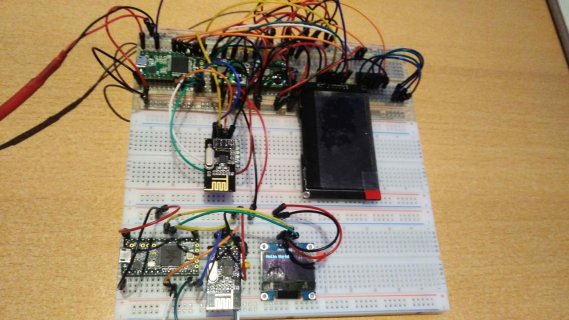
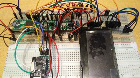
Iam facing some problems with a Teensy 3.1 in combination with a "NRF24L01 2.4GHz - SPI Interface Wireless Transceiver" and an "SSD1306 OLED Display".

The display and the transceiver work both in SPI.

If i use the display only the display works.
If i add the transceiver the display stops displaying.

SCK,DIN,DOUT are shared, CS (SS) is seperate for each device.

Iam sure i have some wrong wiring going on maybe, but i cant figure out where the collision is happening.

If i pull out the Transceiver and unpower/repower the Teensy then the display shows something.
If i pull out the SCK from the Transceiver the display shows artefacts (a bar that gets longer with every received text from the sender. rhytmic)

The sender works fine (Teensy 3.2 and an I2C OLED, so no conflict there).


Code:
// Receiver COM4

/*
SPI - Serial Peripheral Interface
NRF24L01 2.4GHz - SPI Interface Wireless Transceiver
_______________________________________________________________________________________________________________________________________________
Radio NRF24L01						Teensy 3.1                                Description
_______________________________________________________________________________________________________________________________________________
VCC               Power                    3.3v	        red        no SPI Pin
GND               Ground                   3.3v	        black      no SPI Pin

CE                Chip enable              Pin 7        orange     DOUT*                          CE : set high to recieve wireless data, low to send
CSN (SS)          Chip select not          Pin 8        white      DIN*                           CSN : SPI enable pin, set low to listen to SPI bus.

SCK               Serial Clock             Pin 13	yellow     SCK
MOSI              MasterOUTSlaveIN         Pin 11	green	   DOUT	        Data Output
MISO              MasterINSlaveOUT         Pin 12	blue	   DIN		Data Input

IRQ               Interrupt                discon                                                 Active low pin, used only if interrupt is required
*/
/*
_______________________________________________________________________________________________________________________________________________
Display	SSD1306						Teensy 3.1
_______________________________________________________________________________________________________________________________________________
GND               Power                    3.3v	        red        no SPI Pin
VCC               Ground                   3.3v         black      no SPI Pin
RES               Reset                    Pin 23       blue       no SPI Pin

SDL (SCK)         Serial Clock             Pin 13	yellow     SCK
SDA (MOSI)        Serial Data (In)         Pin 11	green      DOUT
DC                Data Command             Pin 14       orange     DIN
CS  (SS)          Chip select              Pin 15       white      CS
*/


// Display Setup
#include <SPI.h>
#include <RF24.h>
#include <Adafruit_GFX.h>
#include <Adafruit_SSD1306.h>
Adafruit_SSD1306 display(14, 23, 15);  // DC,RESET,CS
RF24 radio(7, 8); // CE,CSN

const byte address[6] = "00001";


void setup() {
	// Display Object
	display.begin(SSD1306_SWITCHCAPVCC);
	display.setRotation(3);
	display.setTextSize(1);
	display.setTextColor(WHITE, BLACK);
	display.clearDisplay();
	display.setCursor(0, 0);
	display.println("Welcome!");
	display.display();

	radio.begin();
	radio.setPALevel(RF24_PA_HIGH);
	radio.openReadingPipe(1, address);
	radio.startListening();
}

void loop() {

	if (radio.available()) {
		char text[32] = "";
		radio.read(&text, sizeof(text));

		display.clearDisplay();
		display.display();
		delay(20);

		display.setCursor(0, 0);
		display.println("Receiving:");
		display.println(text);
		display.display();
		
	}
}
 

Attachments

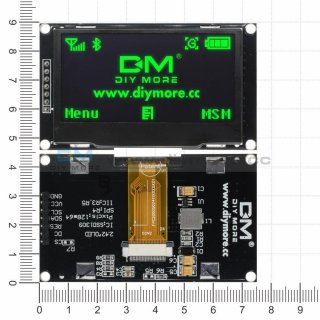
  • 2-42-inch-12864-oled-display-module-iic-i2c-spi-serial-for-arduino-c51-stm32-greenwhiteblueyello.jpg
    2-42-inch-12864-oled-display-module-iic-i2c-spi-serial-for-arduino-c51-stm32-greenwhiteblueyello.jpg
    126.5 KB · Views: 85
  • 20181209_003052.jpg
    20181209_003052.jpg
    132.7 KB · Views: 95
  • 20181209_003148.jpg
    20181209_003148.jpg
    166.6 KB · Views: 75
I recall seeing discussions about this in the past, and suggestions included:

  • Making sure both drivers use SPI_TRANSACTIONS to insure proper sharing of the SPI bus;
  • Using a pull-up resistor on each CS line; (and)
  • Some devices need a tri-state buffer when on a shared SPI bus.
A google search shows the following (note, I just recall the conversations, I don't have the in-depth knowledge of the underlying causes):

 
Hello, thanks for your answer.

I checked in SPI.h and found:

Code:
// SPI_HAS_TRANSACTION means SPI has beginTransaction(), endTransaction(), usingInterrupt(), and SPISetting(clock, bitOrder, dataMode)
[B]#define SPI_HAS_TRANSACTION 1[/B]


For the display i got the latest version of the "Adafruit_SSD1306" library and checked for "SPI_HAS_TRANSACTION" in it.

Adafruit_SSD1306.h (Active Preprocessor Block)
Code:
[B]#if defined(SPI_HAS_TRANSACTION)
  SPISettings  spiSettings;
#endif[/B]
Adafruit_SSD1306.cpp (Both Inactive Preprocessor Blocks)
Code:
Inactive
#if defined(SPI_HAS_TRANSACTION)
 #define SPI_TRANSACTION_START spi->beginTransaction(spiSettings) ///< Pre-SPI
 #define SPI_TRANSACTION_END   spi->endTransaction()              ///< Post-SPI
[B]Active
#else // SPI transactions likewise not present in older Arduino SPI lib
 #define SPI_TRANSACTION_START ///< Dummy stand-in define
 #define SPI_TRANSACTION_END   ///< keeps compiler happy
#endif
[/B]


Inactive
#ifdef SPI_HAS_TRANSACTION
  spiSettings = SPISettings(bitrate, MSBFIRST, SPI_MODE0);
#endif


For the Radio Transceiver i looked into:

RF24_config.h for "SPI_HAS_TRANSACTION"
Code:
Active
[B]#if defined SPI_HAS_TRANSACTION && !defined SPI_UART && !defined SOFTSPI
    #define RF24_SPI_TRANSACTIONS
  #endif[/B]


In RF24.cpp i looked for "RF24_SPI_TRANSACTIONS"

Code:
Inactive
#if defined (RF24_TINY)
	if (ce_pin != csn_pin) {
		digitalWrite(csn_pin,mode);
	} 
	else {
		if (mode == HIGH) {
			PORTB |= (1<<PINB2);  	// SCK->CSN HIGH
			delayMicroseconds(100); // allow csn to settle.
		} 
		else {
			PORTB &= ~(1<<PINB2);	// SCK->CSN LOW
			delayMicroseconds(11);  // allow csn to settle
		}
	}
	// Return, CSN toggle complete
	return;
	
#elif defined(ARDUINO) && !defined (RF24_SPI_TRANSACTIONS)
	// Minimum ideal SPI bus speed is 2x data rate
	// If we assume 2Mbs data rate and 16Mhz clock, a
	// divider of 4 is the minimum we want.
	// CLK:BUS 8Mhz:2Mhz, 16Mhz:4Mhz, or 20Mhz:5Mhz
	
      #if !defined (SOFTSPI)	
		_SPI.setBitOrder(MSBFIRST);
		_SPI.setDataMode(SPI_MODE0);
		_SPI.setClockDivider(SPI_CLOCK_DIV2);
      #endif
#elif defined (RF24_RPi)
      if(!mode)
	    _SPI.chipSelect(csn_pin);
#endif


Also RF24.cpp

Code:
Inactive
 inline void RF24::beginTransaction() {
    #if defined (RF24_SPI_TRANSACTIONS)
    _SPI.beginTransaction(SPISettings(RF24_SPI_SPEED, MSBFIRST, SPI_MODE0));
	#endif
    csn(LOW);
  }

/****************************************************************************/

  inline void RF24::endTransaction() {
    csn(HIGH);
	#if defined (RF24_SPI_TRANSACTIONS)
    _SPI.endTransaction();
	#endif
  }


Since SPI_HAS_TRANSACTION 1 is defined in SPI.h all the other locked #if defined parts should actually be active, right?
Or do i miss something essential here?
Or is just Visual Studio showing it this way but at compile time these parts will be unlocked?

Or do i have to define SPI_HAS_TRANSACTION myself somewhere?

Thanks! :)
 
Also try initializing both CS pins to unasserted (HIGH) at startup, such that the initialization of the first one does not impact the 2nd device.

Something like:
Code:
void setup() {
    pinMode(15, OUTPUT);
    digitalWrite(15, HIGH);
    pinMode(8, OUTPUT);
    digitalWrite(8, HIGH);

    // Display Object
    display.begin(SSD1306_SWITCHCAPVCC);
...
 
So now after spending 2 full afternoons pulling my hair on this multiple SPI devices test i thought before i give up i will just
plug in another "NRF24L01 Transceiver" Module from the 10 that i bought.

Well, it worked immediatly.
I tested all the remaining ones and they all work!

How lucky must i be to pick exactly the faulty one. :rolleyes:

Thanks to everybody who tryd to help! :D
 
Status
Not open for further replies.
Back
Top