
C3D
Active member
Hello Forum,
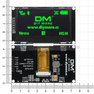
Iam facing some problems with a Teensy 3.1 in combination with a "NRF24L01 2.4GHz - SPI Interface Wireless Transceiver" and an "SSD1306 OLED Display".
The display and the transceiver work both in SPI.
If i use the display only the display works.
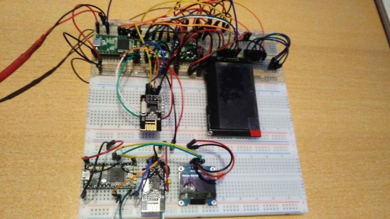
If i add the transceiver the display stops displaying.
SCK,DIN,DOUT are shared, CS (SS) is seperate for each device.
Iam sure i have some wrong wiring going on maybe, but i cant figure out where the collision is happening.
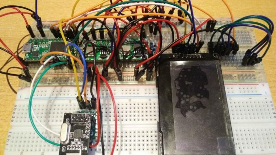
If i pull out the Transceiver and unpower/repower the Teensy then the display shows something.
If i pull out the SCK from the Transceiver the display shows artefacts (a bar that gets longer with every received text from the sender. rhytmic)
The sender works fine (Teensy 3.2 and an I2C OLED, so no conflict there).
Iam facing some problems with a Teensy 3.1 in combination with a "NRF24L01 2.4GHz - SPI Interface Wireless Transceiver" and an "SSD1306 OLED Display".
The display and the transceiver work both in SPI.
If i use the display only the display works.
If i add the transceiver the display stops displaying.
SCK,DIN,DOUT are shared, CS (SS) is seperate for each device.
Iam sure i have some wrong wiring going on maybe, but i cant figure out where the collision is happening.
If i pull out the Transceiver and unpower/repower the Teensy then the display shows something.
If i pull out the SCK from the Transceiver the display shows artefacts (a bar that gets longer with every received text from the sender. rhytmic)
The sender works fine (Teensy 3.2 and an I2C OLED, so no conflict there).
Code:
// Receiver COM4

/*
SPI - Serial Peripheral Interface
NRF24L01 2.4GHz - SPI Interface Wireless Transceiver
_______________________________________________________________________________________________________________________________________________
Radio NRF24L01						Teensy 3.1                                Description
_______________________________________________________________________________________________________________________________________________
VCC               Power                    3.3v	        red        no SPI Pin
GND               Ground                   3.3v	        black      no SPI Pin

CE                Chip enable              Pin 7        orange     DOUT*                          CE : set high to recieve wireless data, low to send
CSN (SS)          Chip select not          Pin 8        white      DIN*                           CSN : SPI enable pin, set low to listen to SPI bus.

SCK               Serial Clock             Pin 13	yellow     SCK
MOSI              MasterOUTSlaveIN         Pin 11	green	   DOUT	        Data Output
MISO              MasterINSlaveOUT         Pin 12	blue	   DIN		Data Input

IRQ               Interrupt                discon                                                 Active low pin, used only if interrupt is required
*/
/*
_______________________________________________________________________________________________________________________________________________
Display	SSD1306						Teensy 3.1
_______________________________________________________________________________________________________________________________________________
GND               Power                    3.3v	        red        no SPI Pin
VCC               Ground                   3.3v         black      no SPI Pin
RES               Reset                    Pin 23       blue       no SPI Pin

SDL (SCK)         Serial Clock             Pin 13	yellow     SCK
SDA (MOSI)        Serial Data (In)         Pin 11	green      DOUT
DC                Data Command             Pin 14       orange     DIN
CS  (SS)          Chip select              Pin 15       white      CS
*/


// Display Setup
#include <SPI.h>
#include <RF24.h>
#include <Adafruit_GFX.h>
#include <Adafruit_SSD1306.h>
Adafruit_SSD1306 display(14, 23, 15);  // DC,RESET,CS
RF24 radio(7, 8); // CE,CSN

const byte address[6] = "00001";


void setup() {
	// Display Object
	display.begin(SSD1306_SWITCHCAPVCC);
	display.setRotation(3);
	display.setTextSize(1);
	display.setTextColor(WHITE, BLACK);
	display.clearDisplay();
	display.setCursor(0, 0);
	display.println("Welcome!");
	display.display();

	radio.begin();
	radio.setPALevel(RF24_PA_HIGH);
	radio.openReadingPipe(1, address);
	radio.startListening();
}

void loop() {

	if (radio.available()) {
		char text[32] = "";
		radio.read(&text, sizeof(text));

		display.clearDisplay();
		display.display();
		delay(20);

		display.setCursor(0, 0);
		display.println("Receiving:");
		display.println(text);
		display.display();

	}
}
")