Hi,
I'm working on my Lab PSU for quite a few months now and switched from a dedicated ADC (MCP3204) to the Teensy 3.5 integrated ADC recently to put the cost down a bit.
Here's a (a bit outdated) schematics, but you'll get an idea what I'm talking about:
https://github.com/mamama1/LabPSU_Darlington/raw/master/Hardware/schematics.pdf
I was wondering if the current circuitry is suitable for voltage measurements using the integrated Teensy 3.5 ADC, as I observed some issues if I don't sample and convert at the lowest possible speed (voltages are being read too low, so I guess the sampling cap doesn't get fully charged fast enough).
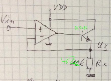
Particularly please look at the first page, bottom right corner. Opamp IC11B with R30 and R32 voltage divider. Please note, that in my current circuit I use 90.9k for R30 and 10.1k for R32. Also, at the output of the opamp, I put a transistor and a 4k7 pulldown transistor, like this:

this is to shift the opamps output (working) voltage up a bit. although it is a rail to rail opamp, it doesn't get all the way down to 0 mV at single supply so without the NPN it was outputting like 5 mV at minimum, which was being read as 50 mV by the software because of the 1:10 voltage divider.
The ADS1115 didn't have any issues measuring this circuitry, I got like 0.1% to 1% error but with the Teensy 3.5 ADC only at the slowest possible sampling- and conversion rate I get decent results which still aren't as good as the ADS1115's ones (like 5 mV off most of the time).
Is there anything I can improve for the Teensy's ADC to make its life easier or is this simply the best I can get with an MCU integrated ADC?
Oh yes, I forgot: I use an external 2.048V precision voltage reference.
Thanks for your thoughts!
I'm working on my Lab PSU for quite a few months now and switched from a dedicated ADC (MCP3204) to the Teensy 3.5 integrated ADC recently to put the cost down a bit.
Here's a (a bit outdated) schematics, but you'll get an idea what I'm talking about:
https://github.com/mamama1/LabPSU_Darlington/raw/master/Hardware/schematics.pdf
I was wondering if the current circuitry is suitable for voltage measurements using the integrated Teensy 3.5 ADC, as I observed some issues if I don't sample and convert at the lowest possible speed (voltages are being read too low, so I guess the sampling cap doesn't get fully charged fast enough).
Particularly please look at the first page, bottom right corner. Opamp IC11B with R30 and R32 voltage divider. Please note, that in my current circuit I use 90.9k for R30 and 10.1k for R32. Also, at the output of the opamp, I put a transistor and a 4k7 pulldown transistor, like this:

this is to shift the opamps output (working) voltage up a bit. although it is a rail to rail opamp, it doesn't get all the way down to 0 mV at single supply so without the NPN it was outputting like 5 mV at minimum, which was being read as 50 mV by the software because of the 1:10 voltage divider.
The ADS1115 didn't have any issues measuring this circuitry, I got like 0.1% to 1% error but with the Teensy 3.5 ADC only at the slowest possible sampling- and conversion rate I get decent results which still aren't as good as the ADS1115's ones (like 5 mV off most of the time).
Is there anything I can improve for the Teensy's ADC to make its life easier or is this simply the best I can get with an MCU integrated ADC?
Oh yes, I forgot: I use an external 2.048V precision voltage reference.
Thanks for your thoughts!
Last edited:

