AidanRTaylor
Active member
Hello, I have a Teensy project that is using a PCM5102 for audio output, I am running the decoded audio into a TPA2012 amplifier and a TPA4411 headphones amp. I have it set out on a PCB (I want to die after reflow soldering those chips with a hot air gun, there is also a BQ24705 which is a 3x3mm 16 pin QFN!!  ) - and everything is working great, however I need to make a few revisions for the next PCB iteration.
Both of the amplifiers are digitally enabled, and I have pins assigned from the Teensy to enable them. I was basically hoping that when I plug in headphones, a switching jack socket will somehow shut off the speaker amplifier, but I can't work out how to do this. Switching headphone jacks all seem to be designed to just re-route an output signal to the headphones (breaking contact to wherever else) but this doesn't work in my context.
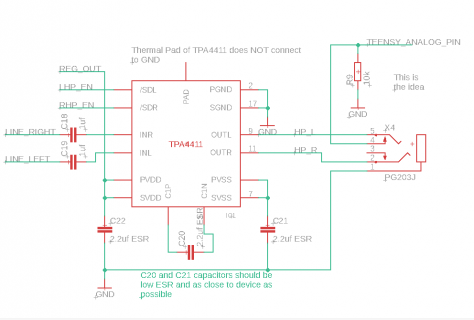
I am wondering if I can perhaps tie one of the sockets switch contacts to an analog pin on the Teensy, along with a 10k pull down resistor. When the headphones are plugged in, the switch is opened which should also pull the pin low, but when the headphones are removed the audio output of the TPA4411 should pull the voltage a little higher. I can use this to switch the TPA2012 on and off.
Does this sound feasible? It seems complicated but I can't think of a simpler way to do it, I should be able to test it with my current set up - diagram included for context:


