
StanfordEE
Well-known member
Continuing my prior work, I wanted to illustrate some ongoing difficulties with jitter as illustrated by some simple examples. For this test, we will use a 1 GHz bandwidth, 5 Gs/s, oscilloscope with 700 MHz bandwidth passive probes.
Here, this is the simplest example of all. Write pulses to a pin and look at the jitter, when overclocking at 240 MHz.
//Teensy 3.6 Test of bit banging jitter.
int startPulsePin = 14;
void setup()
{
pinMode(startPulsePin,OUTPUT); //Our test start pulse for a hypothetical ADC
noInterrupts(); //Turn off interrupts to minimize jitter
}
FASTRUN void loop()
{
digitalWriteFast(startPulsePin,LOW);
digitalWriteFast(startPulsePin,HIGH);
}
So what does one get? In a nutshell, it is a very asymmetrical signal consisting of a low-going pulse of about 31ns at a frequency of 1.3637 MHz. Surprisingly slow repetition rate, but due to the time consumption of the loop.

With persistence mode turned on to capture any possible timing jitter, there is none to be found.

As noted in other threads, the loop timing has a lot to do with the overall timing, so here is a series of ten pulses repeating via in-line code, then the loop executing.
//Teensy 3.6 Test of bit banging jitter.
int startPulsePin = 14;
void setup()
{
pinMode(startPulsePin,OUTPUT); //Our test start pulse for a hypothetical ADC
noInterrupts(); //Turn off interrupts to minimize jitter
}
FASTRUN void loop()
{
digitalWriteFast(startPulsePin,LOW);
digitalWriteFast(startPulsePin,HIGH);
digitalWriteFast(startPulsePin,LOW);
digitalWriteFast(startPulsePin,HIGH);
digitalWriteFast(startPulsePin,LOW);
digitalWriteFast(startPulsePin,HIGH);
digitalWriteFast(startPulsePin,LOW);
digitalWriteFast(startPulsePin,HIGH);
digitalWriteFast(startPulsePin,LOW);
digitalWriteFast(startPulsePin,HIGH);
digitalWriteFast(startPulsePin,LOW);
digitalWriteFast(startPulsePin,HIGH);
digitalWriteFast(startPulsePin,LOW);
digitalWriteFast(startPulsePin,HIGH);
digitalWriteFast(startPulsePin,LOW);
digitalWriteFast(startPulsePin,HIGH);
digitalWriteFast(startPulsePin,LOW);
digitalWriteFast(startPulsePin,HIGH);
digitalWriteFast(startPulsePin,LOW);
digitalWriteFast(startPulsePin,HIGH);
}
One sees the same pulse width, symmetrical duty cycle within the bursts. The frequency of the burst squarewave is 17.24 MHz and the loop frequency is 1.26 MHz. So this clearly illustrates the trade-off of loops versus in-line coding for fast pulse generation.

The pulses are nicely symmetrical.

Now let's try to build a slightly more realistic bit of code, which in my case is to pulse the clock pin of an ADC and read the resulting data. As noted previously, there are lots of issues with port reads, and at present there is no way to read a complete set of bits, already in the right order and position relative to their binary magnitudes beyond 12 bits, and then not while maintaining library compatibility with most x-y LCD or OLED display modules. Even though that sucks, we can still see what is possible before going in and editing/forking the libraries for those displays.
To verify that there is no jitter, create a separate trigger pulse on a different trigger, to match the duration of the burst. Looks solid, no observable jitter.

Despite the difficulty in using port reads, let's see what we can do with port C, which is the only remotely usable one.
//Teensy 3.6 port reads speed test, overclocked 240 MHz
//G. Kovacs, 1/27/19
//CORRECTED PIN C MAPPING!!!
int temp;
int startPulsePin = 39;
byte pinAtable[] = {33,24,3,4}; //PortA, 4 bits
byte pinBtable[] = {16,17,19,18,0,1,32,25}; //PortB, 8 bits NOTE SCRAMBLED pins!!!
byte pinCtable[] = {15,22,23,9.10,13,11,12,35,36,37,38}; //PortC -> 12 bits, but LED is on pin 13, pins all in binary order!!!!
byte pinDtable[] = {2,14,7,8,6,20,21,5}; //PortD, 8 bits in binary order.
byte pinEtable[] = {31,26}; //PordE, 2 bits, in binary order.
void setup() {
for (int i=0; i<12; i++)
{ pinMode(pinCtable,INPUT_PULLUP); }
pinMode(startPulsePin, OUTPUT);
noInterrupts();
}
FASTRUN void loop() {
digitalWriteFast(startPulsePin,LOW); //Make pulse to clock the ADC
digitalWriteFast(startPulsePin,HIGH);
temp = GPIOC_PDIR; //Read the ADC
}
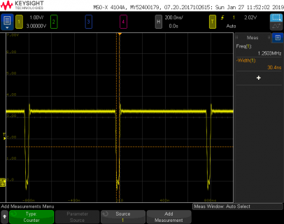
Just as before with just the bit-banged pulse output, but a tiny bit slower due to the port read, we see a low-going pulse approximately 31 ns in width at a frequency of about 16 MHz (15.87 MHz) and an overall repetition rate of 1.25 MHz with no discernable jitter.

As before, add a separate pin to make a trigger so the oscilloscope can see if the bursts of "acquisition" are jittering.
//Teensy 3.6 port reads speed test, overclocked 240 MHz
//G. Kovacs, 1/27/19
//CORRECTED PIN C MAPPING!!!
int temp;
int startPulsePin = 39;
int trigPulsePin = 16;
byte pinAtable[] = {33,24,3,4}; //PortA, 4 bits
byte pinBtable[] = {16,17,19,18,0,1,32,25}; //PortB, 8 bits NOTE SCRAMBLED pins!!!
byte pinCtable[] = {15,22,23,9.10,13,11,12,35,36,37,38}; //PortC -> 12 bits, but LED is on pin 13, pins all in binary order!!!!
byte pinDtable[] = {2,14,7,8,6,20,21,5}; //PortD, 8 bits in binary order.
byte pinEtable[] = {31,26}; //PordE, 2 bits, in binary order.
void setup() {
for (int i=0; i<12; i++)
{ pinMode(pinCtable,INPUT_PULLUP); }
pinMode(startPulsePin, OUTPUT);
pinMode(trigPulsePin, OUTPUT);
noInterrupts();
}
FASTRUN void loop() {
digitalWriteFast(trigPulsePin, LOW);
digitalWriteFast(startPulsePin,LOW); //Make pulse to clock the ADC
digitalWriteFast(startPulsePin,HIGH);
temp = GPIOC_PDIR; //Read the ADC
digitalWriteFast(startPulsePin,LOW); //Make pulse to clock the ADC
digitalWriteFast(startPulsePin,HIGH);
temp = GPIOC_PDIR; //Read the ADC
digitalWriteFast(startPulsePin,LOW); //Make pulse to clock the ADC
digitalWriteFast(startPulsePin,HIGH);
temp = GPIOC_PDIR; //Read the ADC
digitalWriteFast(startPulsePin,LOW); //Make pulse to clock the ADC
digitalWriteFast(startPulsePin,HIGH);
temp = GPIOC_PDIR; //Read the ADC
digitalWriteFast(startPulsePin,LOW); //Make pulse to clock the ADC
digitalWriteFast(startPulsePin,HIGH);
temp = GPIOC_PDIR; //Read the ADC
digitalWriteFast(startPulsePin,LOW); //Make pulse to clock the ADC
digitalWriteFast(startPulsePin,HIGH);
temp = GPIOC_PDIR; //Read the ADC
digitalWriteFast(startPulsePin,LOW); //Make pulse to clock the ADC
digitalWriteFast(startPulsePin,HIGH);
temp = GPIOC_PDIR; //Read the ADC
digitalWriteFast(startPulsePin,LOW); //Make pulse to clock the ADC
digitalWriteFast(startPulsePin,HIGH);
temp = GPIOC_PDIR; //Read the ADC
digitalWriteFast(startPulsePin,LOW); //Make pulse to clock the ADC
digitalWriteFast(startPulsePin,HIGH);
temp = GPIOC_PDIR; //Read the ADC
digitalWriteFast(startPulsePin,LOW); //Make pulse to clock the ADC
digitalWriteFast(startPulsePin,HIGH);
temp = GPIOC_PDIR; //Read the ADC
digitalWriteFast(trigPulsePin,HIGH);
}
See a nice, jitter-free acquisition at about 16 MHz and a loop repetition rate of 1.13 MHz.

If one is willing to give up using the standard libraries for most LCD and OLED displays, it is possible to use the port C reads, in-line, to capture 1024 samples for subsequent analysis. This is the only realistic port, and can accommodate a maximum ADC resolution of 12-bits. Here only the beginning and end of the code is included below…
//Teensy 3.6 port reads speed test, overclocked 240 MHz
//G. Kovacs, 1/27/19
//CORRECTED PIN C MAPPING!!!
int temp;
int startPulsePin = 39;
int trigPulsePin = 16;
byte pinAtable[] = {33,24,3,4}; //PortA, 4 bits
byte pinBtable[] = {16,17,19,18,0,1,32,25}; //PortB, 8 bits NOTE SCRAMBLED pins!!!
byte pinCtable[] = {15,22,23,9.10,13,11,12,35,36,37,38}; //PortC -> 12 bits, but LED is on pin 13, pins all in binary order!!!!
byte pinDtable[] = {2,14,7,8,6,20,21,5}; //PortD, 8 bits in binary order.
byte pinEtable[] = {31,26}; //PordE, 2 bits, in binary order.
double vReal[1024];
void setup() {
for (int i=0; i<12; i++)
{ pinMode(pinCtable,INPUT_PULLUP); }
pinMode(startPulsePin, OUTPUT);
pinMode(trigPulsePin, OUTPUT);
noInterrupts();
}
FASTRUN void loop() {
digitalWriteFast(trigPulsePin, LOW);
digitalWriteFast(startPulsePin,LOW);
digitalWriteFast(startPulsePin,HIGH);
vReal[0] = GPIOC_PDIR; //Read the ADC
digitalWriteFast(startPulsePin,LOW);
digitalWriteFast(startPulsePin,HIGH);
vReal[1] = GPIOC_PDIR; //Read the ADC
digitalWriteFast(startPulsePin,LOW);
digitalWriteFast(startPulsePin,HIGH);
vReal[2] = GPIOC_PDIR; //Read the ADC
*
*
*
digitalWriteFast(startPulsePin,LOW);
digitalWriteFast(startPulsePin,HIGH);
vReal[1022] = GPIOC_PDIR; //Read the ADC
digitalWriteFast(startPulsePin,LOW);
digitalWriteFast(startPulsePin,HIGH);
vReal[1023] = GPIOC_PDIR; //Read the ADC
digitalWriteFast(trigPulsePin,HIGH);
}
One obtains a sample period of 288 ns for a sample rate of 3.4722 Ms/s, which isn't really all that fast.

Next, as previously reported, try using in-line code to capture 1024 samples from a hypothetical ADC using pins 24..39 for up to 16-bits of parallel ADC data by individually reading each bit, shifting it to the correct place in binary, and assembling a sample. Here the code is adjusted for a 10-bit input, and only the beginning and end of the sketch is included below…
//Teensy 3.6 port reads speed test, overclocked 240 MHz
//Brute force bit reads for 10-bit ADC, but scalable with same pins upward to 16 bits.
//G. Kovacs, 1/27/19
int startPulsePin = 17;
int trigPulsePin = 16;
double vReal[1024]; //This needs to be double for the FFT routine in use.
void setup() {
pinMode(startPulsePin,OUTPUT); //Our test start pulse for a hypothetical ADC
pinMode(trigPulsePin,OUTPUT); //Pin for triggering scope at start of each burst
digitalWriteFast(startPulsePin,HIGH);
for (int i = 0; i<16; i++) //use pins 24..39 in this test
{
pinMode(i+24,INPUT_PULLUP); //inputs for ADC using pinmode, LSB = 0
}
noInterrupts();
}
FASTRUN void loop() {
digitalWriteFast(trigPulsePin, LOW);
digitalWriteFast(startPulsePin,LOW);
digitalWriteFast(startPulsePin,HIGH);
vReal[0] = (digitalReadFast(24)<<9)+(digitalReadFast(25)<<8)+(digitalReadFast(26)<<7)+(digitalReadFast(27)<<6)+(digitalReadFast(28)<<5)+(digitalReadFast(29)<<4)+(digitalReadFast(30)<<3)+(digitalReadFast(31)<<2)+(digitalReadFast(32)<<1)+digitalReadFast(33);
digitalWriteFast(startPulsePin,LOW);
digitalWriteFast(startPulsePin,HIGH);
vReal[1] = (digitalReadFast(24)<<9)+(digitalReadFast(25)<<8)+(digitalReadFast(26)<<7)+(digitalReadFast(27)<<6)+(digitalReadFast(28)<<5)+(digitalReadFast(29)<<4)+(digitalReadFast(30)<<3)+(digitalReadFast(31)<<2)+(digitalReadFast(32)<<1)+digitalReadFast(33);
digitalWriteFast(startPulsePin,LOW);
digitalWriteFast(startPulsePin,HIGH);
*
*
*
vReal[1021] = (digitalReadFast(24)<<9)+(digitalReadFast(25)<<8)+(digitalReadFast(26)<<7)+(digitalReadFast(27)<<6)+(digitalReadFast(28)<<5)+(digitalReadFast(29)<<4)+(digitalReadFast(30)<<3)+(digitalReadFast(31)<<2)+(digitalReadFast(32)<<1)+digitalReadFast(33);
digitalWriteFast(startPulsePin,LOW);
digitalWriteFast(startPulsePin,HIGH);
vReal[1022] = (digitalReadFast(24)<<9)+(digitalReadFast(25)<<8)+(digitalReadFast(26)<<7)+(digitalReadFast(27)<<6)+(digitalReadFast(28)<<5)+(digitalReadFast(29)<<4)+(digitalReadFast(30)<<3)+(digitalReadFast(31)<<2)+(digitalReadFast(32)<<1)+digitalReadFast(33);
digitalWriteFast(startPulsePin,LOW);
digitalWriteFast(startPulsePin,HIGH);
vReal[1023] = (digitalReadFast(24)<<9)+(digitalReadFast(25)<<8)+(digitalReadFast(26)<<7)+(digitalReadFast(27)<<6)+(digitalReadFast(28)<<5)+(digitalReadFast(29)<<4)+(digitalReadFast(30)<<3)+(digitalReadFast(31)<<2)+(digitalReadFast(32)<<1)+digitalReadFast(33);
digitalWriteFast(trigPulsePin,HIGH);
}
After taking several minutes to compile (!), this yields a sample rate within the burst of about 2 Ms/s, which is about as fast as this approach could run. Measured as accurately as possible (averaging, careful cursor placement), the sample period is 470 ns for a frequency of 2.1277 Ms/s, which could be more accurately measured and used to "calibrate" the subsequent acquisitions , rather than trying to get a precise timing of, say 2.000000 Ms/s (which would of course be nice).

Working Conclusions:
1) In-line coding for burst acquisition is much faster than looping, and the maximum interrupt-driven speed using intervalTimer is 1Ms/s. However, in-line coding will not deliver typical, neat and tidy sampling rates, such as 1, 2, 5, 10 Ms/s. However, this is something than can be mathematically taken into account later (e.g., scaling an FFT).
2) The achievable sample rates, given all of the Arduino ecosystem constraints (unless I'm missing something) and without having to fork libraries for common LCD and OLED displays due to need for some of the port C pins, are on the order of low Ms/s, specifically about 2.13 Ms/s for 10-bit ADC inputs. This would enable 1 MHz maximum bandwith FFT's on a Teensy 3.6, far beyond the capabilities of the internal ADC's.
3) Port reads, if one is willing to edit libraries and then be strapped to perpetually updating them in sync with their authors, or drifting away, are practically limited to 12 contiguous bits (portC) and the maximum sample rate is not that much better at 3.47 Ms/s. It does not seem worth the hassle at all. No way.
4) There is no jitter seen, although with lower bandwidth oscilloscopes, trigger jitter can falsely show some. Beware of crappy oscilloscopes. You get what you pay for.
5) Directly reading the ADC in either of these methods is going to be faster than SPI for higher-resolution ADC's, but beating, for example, a 10-bit ADC on 15 MHz SPI either way. When one gets up to higher resolution, parallel will win. In general, really fast ADC's do not come with serial outputs for this reason.
6) A relatively simple hardware data acquisition circuit, controlled by the Teensy will be the best option if it is done at reasonable cost. SRAM fed by the ADC, clocked from a crystal oscillator, and addressed using fast counters (e.g., 74HC590 or 74AS867, topping out around 35 Ms/s and 50 Ms/s, respectively, at 5V power) could reach the highest frequencies possible. A counter such as the 74F269 could reach 100 Ms/s, but then SRAM could get a bit pricey, and most affordable parallel (flash) ADC's top out around 40 Ms/s.
Here, this is the simplest example of all. Write pulses to a pin and look at the jitter, when overclocking at 240 MHz.
//Teensy 3.6 Test of bit banging jitter.
int startPulsePin = 14;
void setup()
{
pinMode(startPulsePin,OUTPUT); //Our test start pulse for a hypothetical ADC
noInterrupts(); //Turn off interrupts to minimize jitter
}
FASTRUN void loop()
{
digitalWriteFast(startPulsePin,LOW);
digitalWriteFast(startPulsePin,HIGH);
}
So what does one get? In a nutshell, it is a very asymmetrical signal consisting of a low-going pulse of about 31ns at a frequency of 1.3637 MHz. Surprisingly slow repetition rate, but due to the time consumption of the loop.
With persistence mode turned on to capture any possible timing jitter, there is none to be found.
As noted in other threads, the loop timing has a lot to do with the overall timing, so here is a series of ten pulses repeating via in-line code, then the loop executing.
//Teensy 3.6 Test of bit banging jitter.
int startPulsePin = 14;
void setup()
{
pinMode(startPulsePin,OUTPUT); //Our test start pulse for a hypothetical ADC
noInterrupts(); //Turn off interrupts to minimize jitter
}
FASTRUN void loop()
{
digitalWriteFast(startPulsePin,LOW);
digitalWriteFast(startPulsePin,HIGH);
digitalWriteFast(startPulsePin,LOW);
digitalWriteFast(startPulsePin,HIGH);
digitalWriteFast(startPulsePin,LOW);
digitalWriteFast(startPulsePin,HIGH);
digitalWriteFast(startPulsePin,LOW);
digitalWriteFast(startPulsePin,HIGH);
digitalWriteFast(startPulsePin,LOW);
digitalWriteFast(startPulsePin,HIGH);
digitalWriteFast(startPulsePin,LOW);
digitalWriteFast(startPulsePin,HIGH);
digitalWriteFast(startPulsePin,LOW);
digitalWriteFast(startPulsePin,HIGH);
digitalWriteFast(startPulsePin,LOW);
digitalWriteFast(startPulsePin,HIGH);
digitalWriteFast(startPulsePin,LOW);
digitalWriteFast(startPulsePin,HIGH);
digitalWriteFast(startPulsePin,LOW);
digitalWriteFast(startPulsePin,HIGH);
}
One sees the same pulse width, symmetrical duty cycle within the bursts. The frequency of the burst squarewave is 17.24 MHz and the loop frequency is 1.26 MHz. So this clearly illustrates the trade-off of loops versus in-line coding for fast pulse generation.
The pulses are nicely symmetrical.
Now let's try to build a slightly more realistic bit of code, which in my case is to pulse the clock pin of an ADC and read the resulting data. As noted previously, there are lots of issues with port reads, and at present there is no way to read a complete set of bits, already in the right order and position relative to their binary magnitudes beyond 12 bits, and then not while maintaining library compatibility with most x-y LCD or OLED display modules. Even though that sucks, we can still see what is possible before going in and editing/forking the libraries for those displays.
To verify that there is no jitter, create a separate trigger pulse on a different trigger, to match the duration of the burst. Looks solid, no observable jitter.
Despite the difficulty in using port reads, let's see what we can do with port C, which is the only remotely usable one.
//Teensy 3.6 port reads speed test, overclocked 240 MHz
//G. Kovacs, 1/27/19
//CORRECTED PIN C MAPPING!!!
int temp;
int startPulsePin = 39;
byte pinAtable[] = {33,24,3,4}; //PortA, 4 bits
byte pinBtable[] = {16,17,19,18,0,1,32,25}; //PortB, 8 bits NOTE SCRAMBLED pins!!!
byte pinCtable[] = {15,22,23,9.10,13,11,12,35,36,37,38}; //PortC -> 12 bits, but LED is on pin 13, pins all in binary order!!!!
byte pinDtable[] = {2,14,7,8,6,20,21,5}; //PortD, 8 bits in binary order.
byte pinEtable[] = {31,26}; //PordE, 2 bits, in binary order.
void setup() {
for (int i=0; i<12; i++)
{ pinMode(pinCtable,INPUT_PULLUP); }
pinMode(startPulsePin, OUTPUT);
noInterrupts();
}
FASTRUN void loop() {
digitalWriteFast(startPulsePin,LOW); //Make pulse to clock the ADC
digitalWriteFast(startPulsePin,HIGH);
temp = GPIOC_PDIR; //Read the ADC
}
Just as before with just the bit-banged pulse output, but a tiny bit slower due to the port read, we see a low-going pulse approximately 31 ns in width at a frequency of about 16 MHz (15.87 MHz) and an overall repetition rate of 1.25 MHz with no discernable jitter.
As before, add a separate pin to make a trigger so the oscilloscope can see if the bursts of "acquisition" are jittering.
//Teensy 3.6 port reads speed test, overclocked 240 MHz
//G. Kovacs, 1/27/19
//CORRECTED PIN C MAPPING!!!
int temp;
int startPulsePin = 39;
int trigPulsePin = 16;
byte pinAtable[] = {33,24,3,4}; //PortA, 4 bits
byte pinBtable[] = {16,17,19,18,0,1,32,25}; //PortB, 8 bits NOTE SCRAMBLED pins!!!
byte pinCtable[] = {15,22,23,9.10,13,11,12,35,36,37,38}; //PortC -> 12 bits, but LED is on pin 13, pins all in binary order!!!!
byte pinDtable[] = {2,14,7,8,6,20,21,5}; //PortD, 8 bits in binary order.
byte pinEtable[] = {31,26}; //PordE, 2 bits, in binary order.
void setup() {
for (int i=0; i<12; i++)
{ pinMode(pinCtable,INPUT_PULLUP); }
pinMode(startPulsePin, OUTPUT);
pinMode(trigPulsePin, OUTPUT);
noInterrupts();
}
FASTRUN void loop() {
digitalWriteFast(trigPulsePin, LOW);
digitalWriteFast(startPulsePin,LOW); //Make pulse to clock the ADC
digitalWriteFast(startPulsePin,HIGH);
temp = GPIOC_PDIR; //Read the ADC
digitalWriteFast(startPulsePin,LOW); //Make pulse to clock the ADC
digitalWriteFast(startPulsePin,HIGH);
temp = GPIOC_PDIR; //Read the ADC
digitalWriteFast(startPulsePin,LOW); //Make pulse to clock the ADC
digitalWriteFast(startPulsePin,HIGH);
temp = GPIOC_PDIR; //Read the ADC
digitalWriteFast(startPulsePin,LOW); //Make pulse to clock the ADC
digitalWriteFast(startPulsePin,HIGH);
temp = GPIOC_PDIR; //Read the ADC
digitalWriteFast(startPulsePin,LOW); //Make pulse to clock the ADC
digitalWriteFast(startPulsePin,HIGH);
temp = GPIOC_PDIR; //Read the ADC
digitalWriteFast(startPulsePin,LOW); //Make pulse to clock the ADC
digitalWriteFast(startPulsePin,HIGH);
temp = GPIOC_PDIR; //Read the ADC
digitalWriteFast(startPulsePin,LOW); //Make pulse to clock the ADC
digitalWriteFast(startPulsePin,HIGH);
temp = GPIOC_PDIR; //Read the ADC
digitalWriteFast(startPulsePin,LOW); //Make pulse to clock the ADC
digitalWriteFast(startPulsePin,HIGH);
temp = GPIOC_PDIR; //Read the ADC
digitalWriteFast(startPulsePin,LOW); //Make pulse to clock the ADC
digitalWriteFast(startPulsePin,HIGH);
temp = GPIOC_PDIR; //Read the ADC
digitalWriteFast(startPulsePin,LOW); //Make pulse to clock the ADC
digitalWriteFast(startPulsePin,HIGH);
temp = GPIOC_PDIR; //Read the ADC
digitalWriteFast(trigPulsePin,HIGH);
}
See a nice, jitter-free acquisition at about 16 MHz and a loop repetition rate of 1.13 MHz.
If one is willing to give up using the standard libraries for most LCD and OLED displays, it is possible to use the port C reads, in-line, to capture 1024 samples for subsequent analysis. This is the only realistic port, and can accommodate a maximum ADC resolution of 12-bits. Here only the beginning and end of the code is included below…
//Teensy 3.6 port reads speed test, overclocked 240 MHz
//G. Kovacs, 1/27/19
//CORRECTED PIN C MAPPING!!!
int temp;
int startPulsePin = 39;
int trigPulsePin = 16;
byte pinAtable[] = {33,24,3,4}; //PortA, 4 bits
byte pinBtable[] = {16,17,19,18,0,1,32,25}; //PortB, 8 bits NOTE SCRAMBLED pins!!!
byte pinCtable[] = {15,22,23,9.10,13,11,12,35,36,37,38}; //PortC -> 12 bits, but LED is on pin 13, pins all in binary order!!!!
byte pinDtable[] = {2,14,7,8,6,20,21,5}; //PortD, 8 bits in binary order.
byte pinEtable[] = {31,26}; //PordE, 2 bits, in binary order.
double vReal[1024];
void setup() {
for (int i=0; i<12; i++)
{ pinMode(pinCtable,INPUT_PULLUP); }
pinMode(startPulsePin, OUTPUT);
pinMode(trigPulsePin, OUTPUT);
noInterrupts();
}
FASTRUN void loop() {
digitalWriteFast(trigPulsePin, LOW);
digitalWriteFast(startPulsePin,LOW);
digitalWriteFast(startPulsePin,HIGH);
vReal[0] = GPIOC_PDIR; //Read the ADC
digitalWriteFast(startPulsePin,LOW);
digitalWriteFast(startPulsePin,HIGH);
vReal[1] = GPIOC_PDIR; //Read the ADC
digitalWriteFast(startPulsePin,LOW);
digitalWriteFast(startPulsePin,HIGH);
vReal[2] = GPIOC_PDIR; //Read the ADC
*
*
*
digitalWriteFast(startPulsePin,LOW);
digitalWriteFast(startPulsePin,HIGH);
vReal[1022] = GPIOC_PDIR; //Read the ADC
digitalWriteFast(startPulsePin,LOW);
digitalWriteFast(startPulsePin,HIGH);
vReal[1023] = GPIOC_PDIR; //Read the ADC
digitalWriteFast(trigPulsePin,HIGH);
}
One obtains a sample period of 288 ns for a sample rate of 3.4722 Ms/s, which isn't really all that fast.
Next, as previously reported, try using in-line code to capture 1024 samples from a hypothetical ADC using pins 24..39 for up to 16-bits of parallel ADC data by individually reading each bit, shifting it to the correct place in binary, and assembling a sample. Here the code is adjusted for a 10-bit input, and only the beginning and end of the sketch is included below…
//Teensy 3.6 port reads speed test, overclocked 240 MHz
//Brute force bit reads for 10-bit ADC, but scalable with same pins upward to 16 bits.
//G. Kovacs, 1/27/19
int startPulsePin = 17;
int trigPulsePin = 16;
double vReal[1024]; //This needs to be double for the FFT routine in use.
void setup() {
pinMode(startPulsePin,OUTPUT); //Our test start pulse for a hypothetical ADC
pinMode(trigPulsePin,OUTPUT); //Pin for triggering scope at start of each burst
digitalWriteFast(startPulsePin,HIGH);
for (int i = 0; i<16; i++) //use pins 24..39 in this test
{
pinMode(i+24,INPUT_PULLUP); //inputs for ADC using pinmode, LSB = 0
}
noInterrupts();
}
FASTRUN void loop() {
digitalWriteFast(trigPulsePin, LOW);
digitalWriteFast(startPulsePin,LOW);
digitalWriteFast(startPulsePin,HIGH);
vReal[0] = (digitalReadFast(24)<<9)+(digitalReadFast(25)<<8)+(digitalReadFast(26)<<7)+(digitalReadFast(27)<<6)+(digitalReadFast(28)<<5)+(digitalReadFast(29)<<4)+(digitalReadFast(30)<<3)+(digitalReadFast(31)<<2)+(digitalReadFast(32)<<1)+digitalReadFast(33);
digitalWriteFast(startPulsePin,LOW);
digitalWriteFast(startPulsePin,HIGH);
vReal[1] = (digitalReadFast(24)<<9)+(digitalReadFast(25)<<8)+(digitalReadFast(26)<<7)+(digitalReadFast(27)<<6)+(digitalReadFast(28)<<5)+(digitalReadFast(29)<<4)+(digitalReadFast(30)<<3)+(digitalReadFast(31)<<2)+(digitalReadFast(32)<<1)+digitalReadFast(33);
digitalWriteFast(startPulsePin,LOW);
digitalWriteFast(startPulsePin,HIGH);
*
*
*
vReal[1021] = (digitalReadFast(24)<<9)+(digitalReadFast(25)<<8)+(digitalReadFast(26)<<7)+(digitalReadFast(27)<<6)+(digitalReadFast(28)<<5)+(digitalReadFast(29)<<4)+(digitalReadFast(30)<<3)+(digitalReadFast(31)<<2)+(digitalReadFast(32)<<1)+digitalReadFast(33);
digitalWriteFast(startPulsePin,LOW);
digitalWriteFast(startPulsePin,HIGH);
vReal[1022] = (digitalReadFast(24)<<9)+(digitalReadFast(25)<<8)+(digitalReadFast(26)<<7)+(digitalReadFast(27)<<6)+(digitalReadFast(28)<<5)+(digitalReadFast(29)<<4)+(digitalReadFast(30)<<3)+(digitalReadFast(31)<<2)+(digitalReadFast(32)<<1)+digitalReadFast(33);
digitalWriteFast(startPulsePin,LOW);
digitalWriteFast(startPulsePin,HIGH);
vReal[1023] = (digitalReadFast(24)<<9)+(digitalReadFast(25)<<8)+(digitalReadFast(26)<<7)+(digitalReadFast(27)<<6)+(digitalReadFast(28)<<5)+(digitalReadFast(29)<<4)+(digitalReadFast(30)<<3)+(digitalReadFast(31)<<2)+(digitalReadFast(32)<<1)+digitalReadFast(33);
digitalWriteFast(trigPulsePin,HIGH);
}
After taking several minutes to compile (!), this yields a sample rate within the burst of about 2 Ms/s, which is about as fast as this approach could run. Measured as accurately as possible (averaging, careful cursor placement), the sample period is 470 ns for a frequency of 2.1277 Ms/s, which could be more accurately measured and used to "calibrate" the subsequent acquisitions , rather than trying to get a precise timing of, say 2.000000 Ms/s (which would of course be nice).
Working Conclusions:
1) In-line coding for burst acquisition is much faster than looping, and the maximum interrupt-driven speed using intervalTimer is 1Ms/s. However, in-line coding will not deliver typical, neat and tidy sampling rates, such as 1, 2, 5, 10 Ms/s. However, this is something than can be mathematically taken into account later (e.g., scaling an FFT).
2) The achievable sample rates, given all of the Arduino ecosystem constraints (unless I'm missing something) and without having to fork libraries for common LCD and OLED displays due to need for some of the port C pins, are on the order of low Ms/s, specifically about 2.13 Ms/s for 10-bit ADC inputs. This would enable 1 MHz maximum bandwith FFT's on a Teensy 3.6, far beyond the capabilities of the internal ADC's.
3) Port reads, if one is willing to edit libraries and then be strapped to perpetually updating them in sync with their authors, or drifting away, are practically limited to 12 contiguous bits (portC) and the maximum sample rate is not that much better at 3.47 Ms/s. It does not seem worth the hassle at all. No way.
4) There is no jitter seen, although with lower bandwidth oscilloscopes, trigger jitter can falsely show some. Beware of crappy oscilloscopes. You get what you pay for.
5) Directly reading the ADC in either of these methods is going to be faster than SPI for higher-resolution ADC's, but beating, for example, a 10-bit ADC on 15 MHz SPI either way. When one gets up to higher resolution, parallel will win. In general, really fast ADC's do not come with serial outputs for this reason.
6) A relatively simple hardware data acquisition circuit, controlled by the Teensy will be the best option if it is done at reasonable cost. SRAM fed by the ADC, clocked from a crystal oscillator, and addressed using fast counters (e.g., 74HC590 or 74AS867, topping out around 35 Ms/s and 50 Ms/s, respectively, at 5V power) could reach the highest frequencies possible. A counter such as the 74F269 could reach 100 Ms/s, but then SRAM could get a bit pricey, and most affordable parallel (flash) ADC's top out around 40 Ms/s.
")
