Teensy as USB Audio I2S interface for DAC implementation

barsk

Member
I have been researching building (on a hobby level) a serious USB DAC. Upon trying to find a suitable USB Audio I2S bridge chip, which has proven a bit tricky, I realised that the Teensy has this functionality built in. As I have a Teensy LC lying around I decided to give it a try. 44.1Khz/16 bit is the target for this project, leaving higher resolutions for future improvements, or when Paul has the time to fix the support for these ;)

Design goals is to combat jitter as much as possible, feed the I2S lines to a PCM1794A or 1792A DAC and mate that with a high quality analog stage for output.

Questions:
* Will I be able to get I2S data from the teensy as a USB Audio Bridge? The docs mentions specific codecs/DACS that are supported, but I assume any I2S-based DAC can be used? Docs are a bit unclear on that.
* Is the actual sample frequency now 44.1KHz and not still 44117.64706? Another thread mentions problems with Macs and a solution to this was (as understood) to correct the sampling frequency...
* Can the extracted MCLK line be used as a jitter "free" clock source, or do I need to reclock the data stream externally to actually reduce jitter problems?
* Will a Teensy LC suffice for this, or do I need a higher version?

One possible solution to create a higher quality bridge without dependency on the Teensy derived clock might be to use a FIFO queue between the teensy and DAC, as an asynchronous buffer (independent read/write), and clock the DAC from a local quarts oscillator with a "perfect" 44.1Khz rate. The DAC would then be able to chew its audio data from the fifo on its own, with jitter only depending on the quality of the local oscillator.
This scenario has the problem of buffer under/overrun over time if the clocks differ.

* Is there a possibility to ask the teensy USB audio bridge to slow down or speed up data transfer from host a bit, using it's adaptive feedback on the USB audio protocol? In that case we could let the teensy keep filing up the fifo just enough.

These ideas are specualative and theoretical at the moment, so much may change...
 
One possible solution to create a higher quality bridge without dependency on the Teensy derived clock might be to use a FIFO queue between the teensy and DAC, as an asynchronous buffer (independent read/write), and clock the DAC from a local quarts oscillator with a "perfect" 44.1Khz rate. The DAC would then be able to chew its audio data from the fifo on its own, with jitter only depending on the quality of the local oscillator.
This scenario has the problem of buffer under/overrun over time if the clocks differ.
You could lock a low-bandwidth PLL to the FIFO write clock and use its output as the FIFO read clock. On average, the PLL's frequency will exactly equal that of the input clock. Thus, no over / under run assuming FIFO is large enough to swallow the jitter.

Jitter is reduced due to low-pass phase transfer function of PLL.

However, phase transfer function from VCO to PLL's output is high-pass. So, PLL needs a good VCO.
 
Yes, that might work. However a PLL is adjusting the clock constantly, and that equals jitter...

An another more low level (hardcore!) approach I was considering if it is possible to modify the usb_dev.c code that handles the read buffers of the USB Audio code. If that code was altered to feed the external FIFO queue instead of local RAM, then the FIFO overrun/overrun problem would be solved! I am considering a FIFO chip like the SN74ALVC7806 which is 256x18 bit. So it would hold 256 16 bit samples plus a bit for Left/Right. The data pins of the FIFO chip as well as the Full, Empty, Programmable Almost-Full/Almost-EmptyFlag can be access via the usual GPIO pins.
 
Yes, that might work. However a PLL is adjusting the clock constantly, and that equals jitter...
No, the input jitter (aka phase noise) is attenuated by the LPF characteristics of the PLL. So, any input phase noise that's above the filter's cutoff frequency will be reduced.

As mentioned, the PLL is high-pass with respect to VCO phase noise. So, optimal jitter performance is achieved by adjusting the filter's cutoff to minimize total output jitter based on input jitter characteristics and VCO phase noise specs.

That's how it's been done for decades in digital communications. And, if done properly, results lower total output jitter than input jitter.


An another more low level (hardcore!) approach I was considering if it is possible to modify the usb_dev.c code that handles the read buffers of the USB Audio code. If that code was altered to feed the external FIFO queue instead of local RAM, then the FIFO overrun/overrun problem would be solved!
OK, what will then provide clean clock required for jitter attenuation?
 
No, the input jitter (aka phase noise) is attenuated by the LPF characteristics of the PLL. So, any input phase noise that's above the filter's cutoff frequency will be reduced.
As mentioned, the PLL is high-pass with respect to VCO phase noise. So, optimal jitter performance is achieved by adjusting the filter's cutoff to minimize total output jitter based on input jitter characteristics and VCO phase noise specs.
That's how it's been done for decades in digital communications. And, if done properly, results lower total output jitter than input jitter.
Well, obviously you are more experienced than me in the subject, so I will have a humble stance in the matter. However, I would argue that any clock that is non-fixed is contributing to jitter. Jitter is by definition a clock that is not fixed in time and therefore contributing to nonlinear recreation of the sound wave in the DAC. Even though the "incoming" jitter is reduced by the PLL method, it is of no concern. Actually the jitter could be of any magnitude as long as it is low enough to not read the bits wrongly, i.e. transmission errors. Once the bits are stored in the FIFO the DAC can read it independently of the input stage.

OK, what will then provide clean clock required for jitter attenuation?
The "output stage", comprised of a local high quality 44.1Khz clock totally independent of the Teensy MCLK, the FIFO's read side and a DAC. If all audio data in the FIFO has survived the transmission without errors we are then free to read it independently. Any jitter would then be produced by the local clock alone.

The idea is to isolate the input stage (teensy + USB Audio inteface + FIFO buffer hack) from the output stage (local clock + FIFO + DAC). The FIFO would then act as an intermediary storage with asynchronous and independent access from both sides. The DAC can be said being a master in the system as it consumes audio data and depletes the FIFO. The teensy can read the "almost full/almost empty" flags from the FIFO and keep it filled by the same means it would keep its original RAM based buffers filled. That is by adaptive feedback to the USB host, which is already in place.

Does this make sense?
 
The fact is that any clock source is going to have phase noise -- even your hypothetical “high quality 44.1Khz clock”. The goal of good engineering is to manage it to the point where it doesn’t matter.

PLLs are an essential building block of all digital audio systems. You’re not breaking any new ground here; the subject has been thoroughly analyzed and implemented. Personally, I’d be more concerned about the inevitable FIFO overruns / underruns that will definitely happen with your asynchronous approach then with any alleged audio effects due to jitter that you think you hear.
 
In fact, I might have been reinventing the wheel. These ideas, as you imply, are not new ground as it seems. They are already implemented in the XMOS chips, with FIFOS even. Just found that out... :)

They rely on a local master clock that controls both the DAC and the XMOS chip, and any discrepancy between clock speeds host vs device is handled by the adaptive USB synchronization. Well, that implementation is not identical with my thoughts, but the net results is - to clock the DAC with a steady clean master clock that is not in itself syncing with external sources (e.g PLL).

The easy route would be to go for the XMOS and build a PCB with it. But I might try the teeensy + external FIFO just for the heck of it. As you mention, getting the FIFO to not go into over/underrun may be harder than it looks though. I might need a bigger parallell FIFO than 265x16 also...
 
To answer a few of your original questions...

Will a Teensy LC suffice for this, or do I need a higher version?

Short answer, no. You need at least Teensy 3.2.

All the existing audio code requires Teensy 3.0 or higher. Most newer features have been tested only on Teensy 3.2, 3.5 and 3.6.

Teensy LC isn't supported by any of the code written today. While running this on LC might theoretically be possible, you'll have quite a challenge. The DMA is completely different.


* Will I be able to get I2S data from the teensy as a USB Audio Bridge?

You certainly could run code similar to the example. In Arduino, click File > Examples > Audio > HardwareTesting > PassThroughUSB.


The docs mentions specific codecs/DACS that are supported, but I assume any I2S-based DAC can be used? Docs are a bit unclear on that.

If you haven't seen the tutorial, I highly recommend doing this first to learn how the audio stuff works.

https://www.pjrc.com/store/audio_tutorial_kit.html

Generally, you use separate objects for the I2S input & output, and the codec control. So the I2S input is generic - used with all codecs (at least all with I2S).


* Is the actual sample frequency now 44.1KHz and not still 44117.64706? Another thread mentions problems with Macs and a solution to this was (as understood) to correct the sampling frequency...

If you use the master I2S, yes, the sample rate is 44.11764706 kHz (48 MHz / 1088).

If you use the slave I2S, the sample rate is whatever you drive onto the LRCLK pin.
 
They rely on a local master clock that controls both the DAC and the XMOS chip, and any discrepancy between clock speeds host vs device is handled by the adaptive USB synchronization.
That’s an interesting technique. It is, in fact, implementing a PLL of sorts. But, it’s adjusting the input (sample) rate of the audio data to match the fixed output clock (rather than vice versa). As long as you’re OK with whatever effects changing the rate of the audio sampling causes, it seems viable. Kind of like playing a phonograph record or audio tape (yea, I’m that old) at a different speed.

Of course, it won’t work with streaming data because you don’t get to change the sample rate. But as long as the material is pre-recorded, you at least won’t over / under run the FIFO.
 
To answer a few of your original questions...

Thanks Paul. I'll need to get an upgraded Teensy then. :)
I do have a 3.5 here, but it's already destined for another project. Will do for testing though. And thanks for the workshop.pdf links. It clearifies some things I did'nt grasp initially.

Regarding my ideas for a FIFO intermediate buffer to isolate the decoding phase of the audio with a local clean clock. Is is worth looking into, and can the FIFOs be handled from the usb_dev.c code with some hack?
In fact, if the actual clock the Teensy uses is steady enough, and not having too much of a spread spectrum (aka phase noise, aka jitter) maybe my whole buffering scheme is moot. I might be chasing mosquitos with a hammer here...

If you use the slave I2S, the sample rate is whatever you drive onto the LRCLK pin.
Ah, need to investigate that further. Does that mean the USB synchronization feedback is dependent of the LRCLK pin in slave mode? Meaning I could have a local clean clock at 44.1 KHz driving that, without any side effects? For instance buffer under/overruns etc..?
 
That’s an interesting technique. It is, in fact, implementing a PLL of sorts. But, it’s adjusting the input (sample) rate of the audio data to match the fixed output clock (rather than vice versa). As long as you’re OK with whatever effects changing the rate of the audio sampling causes, it seems viable. Kind of like playing a phonograph record or audio tape (yea, I’m that old) at a different speed.

Of course, it won’t work with streaming data because you don’t get to change the sample rate. But as long as the material is pre-recorded, you at least won’t over / under run the FIFO.
I might be as old as you! VHS was kind of the new tech when I was a teenager. ;)

You're right about streaming data. Didn't think of that. If the clocks differ to much we are bound for under/overrun at some point...
 
It would seem that my idea of an asynchronous I2S FIFO and reclocker has been invented already. This happens to me a lot.. :)
This is basically the same idea I had (minus the USB interface) in two incarnations. Both with forums that has 300-400 pages each, so it obviously has caused a bit of stir in the DIY communities.

Ian's I2S FIFO Project
Kali FIFO Buffer & Reclocker (this one is based on Ian's work)
 
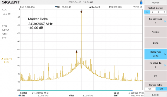
I know I'm resurrecting an old thread, but I just measured the MCLK spectrum on a T4.0 so can show what it actually looks like:

T4_24.576MHz_spurs.png

This was with TDM at 48kSPS, BTW.

It strikes me that for best quality a separate I2S/TDM clock source would be needed, as the on-chip PLL's are not super performant
as those spurs show.

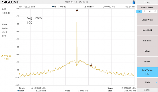
With a 6.144MHz crystal oscillator I get:

Prop-6.144MHz-xtal.png
(different frequency scaling, note).

Which I think is basically the PLL performance of the spectrum analyser itself (note - no big spurs, so its clearly a better PLL than in the i.RT1062)
 
Back
Top