WS2812Serial and Serial1 Conflict

Status
Not open for further replies.

IMI4tth3w

Member
Hello everyone,

I am currently working on a project that involves 2 Teensy 3.5's. They communicate using Serial1 UART over RS485.

The slave teensy is using WS2812Serial library and pin 32 (Serial4)

Now i wrote a simple communication interface to send light data from the Master to the slave. The data transfer has been tested working great. However when i try to update my light bus using the LEDBus0.show() command, i run into problems. Here is a sample below:

Code:
#define SLAVE_ID 1

#define LED_BUS_0_PIN 32
#define LED_BUS_0_NUM 50

byte drawingMemoryBus0[LED_BUS_0_NUM * 3];         //  3 bytes per LED
DMAMEM byte displayMemoryBus0[LED_BUS_0_NUM * 12]; // 12 bytes per LED

WS2812Serial LEDBus0(LED_BUS_0_NUM, drawingMemoryBus0, displayMemoryBus0, LED_BUS_0_PIN, WS2812_GRB);


uint8_t Serial1Instruction = 0; // Stores the current Serial instruction
uint8_t Serial1Buffer[256]; // Serial1 Buffer
uint8_t Serial1BufferIndex = 0; // Serial1 Buffer Index

void RS485Serial1Reset() {
  Serial1Instruction = 0;
  Serial1BufferIndex = 0;
}

void Serial1Update() {
  if(Serial1.available()){
    elapsedMicros Serial1Time=0; // used to keep track of time spent in the serial update
    while(Serial1.available() && Serial1Time < SERIAL1_LOOP_TIMEOUT){
      if (Serial1Instruction == 0){
        Serial1Instruction = Serial1.read();
      }
      
      switch(Serial1Instruction){
        case(0x10): // led update
          if(Serial1.available() >= 203) { // 50 lights of data is 203 bytes. wait for all light data to fill buffer
            Serial.println(Serial1.available());
            Serial1.readBytes(Serial1Buffer, 203);
            if (Serial1Buffer[0] == SLAVE_ID) {
              uint8_t pixelIndex = 4;
              for (uint8_t i = 0; i < Serial1Buffer[2]; i++) {
                if(Serial1Buffer[1] == 0)
                  LEDBus0.setPixel(i, Serial1Buffer[pixelIndex], Serial1Buffer[pixelIndex + 1], Serial1Buffer[pixelIndex + 2]);
                else if(Serial1Buffer[1] == 1);
                  //LEDBus1.setPixel(i, Serial1Buffer[pixelIndex], Serial1Buffer[pixelIndex + 1], Serial1Buffer[pixelIndex + 2]);
                pixelIndex += 4;
              }
              if (Serial1Buffer[1] == 0)
                LEDBus0.show(); // show light bus 0
              else if (Serial1Buffer[1] == 1);
                //LEDBus1.show(); // show light bus 1
            }
            RS485Serial1Reset();
          }
          break;

        default:
          RS485Serial1Reset();
          break;
      }
    }
  }
}

The Serial1Update() function is called every loop in the main loop.

Now if comment out "LEDBus0.show();" from this code, the Serial1 data transfer works just fine (but no led updates obviously). But when i uncomment this, my Serial1 bus goes crazy.

It appears as if the Serial1 and Serial4 busses are sharing memory somewhere. My guess is that the data that is supposed to go to the Serial4 Light bus, ends up being pulled in by my Serial1Update() function, throwing everything off. At least thats what it seems like is happening.

Using the OctoWS2811 library is not an option either as i need the PWM outputs for something else. Looking for a non-blocking light solution as well.

I think the TLDR question here, is do i lose the Serial1 functionality, even if i only want to use the WS2812Serial library on Pin 32 (Serial4) due to some memory sharing between the hardware serial ports?
 
I think the TLDR question here, is do i lose the Serial1 functionality, even if i only want to use the WS2812Serial library on Pin 32 (Serial4) due to some memory sharing between the hardware serial ports?

To answer your question: no, you shouldn't lose Serial1 when WS2812Serial uses Serial4. Not due to memory sharing or any other reason. They're supposed to be independent and able to work simultaneously, without any resource conflict.


Normally I don't investigate unless you provide a complete program I can copy into Arduino to reproduce the problem. I did copy your code into Arduino, but it's not a complete program which compiles, much less gives me a way to quickly reproduce the issue.

In this case, I decided to write a quick test to check. Here's the code I tried.

Code:
#include <WS2812Serial.h>

const int numled = 5;
const int pin = 32;  // Serial4 on Teensy 3.5

byte drawingMemory[numled*3];
DMAMEM byte displayMemory[numled*12];

WS2812Serial leds(numled, displayMemory, drawingMemory, pin, WS2812_GRB);

void setup() {
  leds.begin();
  leds.setPixel(0, 0x5AA566);
  leds.setPixel(1, 0x88BBC6);
  leds.setPixel(2, 0x123456);
  leds.setPixel(3, 0x789ABC);
  leds.setPixel(4, 0x00FFF0);
  Serial1.begin(115200);
}

void loop() {
  leds.show();
  Serial1.println("Hi");
  delay(10);
}

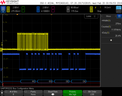
When I run this on a Teensy 3.5, here are the waveforms I see on pins 1 and 32.

file.png

Seems pretty clear that WS2812Serial is able to transmit data on pin 32 (Serial4) while Serial1.println() is able to send a string on pin 1.

This doesn't necessarily mean there isn't an unknown bug lurking. But hopefully this can give you an idea of the sort of code you need to post, if you want me to investigate further. Please, trim it to the smallest code which reproduces the problem, and double check that the code you post here really does compile when copied back into a blank Arduino window and really does reproduce the problem.
 
Hi Paul,

Thank you for your quick and thorough reply.

I apologize for not providing a working example. I should have known to test this out in a simple example such as the one you provided. (I partially blame how cold it was in the office today lol)

I will do more testing tomorrow when i get back in the office and follow up.

Thanks

-Matt
 
Hi Paul,

Just as an update, it looks like the issue is in my handling of serial data.

I have not located the specific issue in the original code i uploaded, but I wrote a new program that is similar, and working just fine.

Here is the code for the Master

Code:
// Master

// Master TX -> Slave RX for Serial1

const int numled = 50;

void setup() {
  Serial1.begin(6000000);
}

void loop() {
  uint8_t someData[numled*3+1];
  someData[0] = 0x10; // load our instruction
  someData[1] = numled; // load our number of LEDs
  
  // load some data into our array
  for(int i = 2; i < numled*3+2; i++) 
    someData[i] = random(255); 

  // write the data
  //for(int i = 0; i < numled*3+2; i++) 
    Serial1.write(someData, numled*3+2); 
  
  
  delay(1000);
}

Here is the code for the Slave

Code:
// Slave

// Slave RX <- Master TX for Serial1

#include <WS2812Serial.h>

const int maxnumled = 50;
const int pin = 32;  // Serial4 on Teensy 3.5

byte drawingMemory[maxnumled*3];
DMAMEM byte displayMemory[maxnumled*12];

uint8_t SerialInstruction = 0;
uint8_t numled = 0;

WS2812Serial leds(maxnumled, displayMemory, drawingMemory, pin, WS2812_GRB);

void setup() {
  leds.begin();
  Serial1.begin(6000000);
  pinMode(3, OUTPUT); // debug pin
  pinMode(4, OUTPUT); // debug pin
  pinMode(5, OUTPUT); // debug pin
}

void loop() {
  if(Serial1.available()){
    int byteCount = 0;
    if(SerialInstruction == 0) {
      digitalWriteFast(5, HIGH);
      SerialInstruction = Serial1.read(); // first byte is the instruction
      byteCount++;
      delayMicroseconds(1); // some delay to see the pulse on pin 5
      digitalWriteFast(5, LOW);
    }

    switch(SerialInstruction){
      case(0x10): // led update instruction
        if(numled == 0)
          numled = Serial1.read(); // second byte is number of leds
          
        else if(Serial1.available() >= numled*3){
          digitalWriteFast(4, HIGH); // set debug pin high

          uint32_t pixelData[numled]; // temp variable to store led data
          
          // read the data for numled leds
          for(int i = 0; i < numled; i++){
            pixelData[i] = Serial1.read() | Serial1.read() << 8 | Serial1.read() << 16;
            byteCount += 3;
          }
          
          // set pixel colors
          for(int i = 0; i < numled; i++)
            leds.setPixel(i, pixelData[i]);
      
          // show the leds
          leds.show();

          SerialInstruction = 0; // reset our serial instruction
          numled = 0; // set number of leds back to 0
          
          digitalWriteFast(4, LOW); // set debug pin low
        }
        break;
        
      default:
        digitalWriteFast(3, HIGH);
        delayMicroseconds(1);
        Serial1.clear();
        SerialInstruction = 0;
        digitalWriteFast(3, LOW);
        break;
    }
  }
}

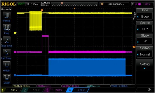
Here is a scope shot

Ch1 - Serial data from Master to Slave
ch3 - pin4 of slave showing time spent in serial update function
ch4 - pin32 light data output

screen.jpg

Everything here is working as intended.

There are some inherent issues that can come about with the way i have designed the serial protocol, but in this simple form it is working. I just did it this way to more closely emulate the original software and what i was trying to accomplish.

So it looks like there are no issues with the WS2812Serial and using Serial1.

Thank you again for the quick response and example you provided.


On another note, any recommendations for resources in developing my own serial protocol? I was looking into ModBus RTU, but its a bit too specific i think for what i want to do. Also, sending tons of LED data is a fairly difficult task in itself that made MosBus RTU less appealing of an option.
 
MIDI is probably the most popular serial protocol for unidirectional data flow. Having 1 bit dedicated to indicating the start of message is simple, but "wastes" 1/8th of the bandwidth. The same can be said of the start bit for asynchronous serial in general. Sometimes simplest is best.

Some people use a MIDI-like scheme with 9 bits. Teensyduino has support for 9 bits, but it's not enabled by default because it doubles the memory usage. If you go that route, you'll need to edit the core library to enable 9 bit support.

Many protocols use reserved bytes. ASCII-based protocols are one subset. Others are more like raw binary, but use 2 or more byte to substitute when the reserved bytes are needed inside data. The huge downside is unknown total data size, worst case expanded 2X. Sometimes, often times, having all cases 12% longer is more desirable than having most as efficient as possible, but a tiny chance of 50% overhead.

Modbus RTU is widespread, probably only because it's so very old and for a very long time was the only "open" protocol in a market filled with closed & tightly guarded serial protocols. But the RTU mode for Modbus requires rather tight timing, since a very brief idle time on the line is used to mark the beginning of each message. While that may seem efficient, for the short message lengths usually used on Modbus, those idle times add up to similar overhead as other schemes.

There aren't any perfect answers, only a lot of less than ideal trade-offs to be made.

But one other small piece of advice. If you do half-duplex RS485 (the most common way) where you do communicate in both directions, make sure that you always wait a brief delay before transmitting. Many people (and some large corporations) have made the mistake of receiving a request, processing it, and sending a reply as quickly as possible. If you turn on your transmitter without any delay, there's a chance you might drive the line in the fraction of a time time where the sender still has its transmitter turned on.

Interesting. Sounds like there really isn't an end all be all Serial protocol. I will keep moving forward with my own findings and implementation then.

I am using half-duplex RS485. Thanks for the tip on the tranmitter enable. In some simple testing, i've found that it is less than 1us from the last edge of the last bit on the TX and the falling edge of the TX enable pin. I should be able to easily avoid this in software. Thank you
 
Status
Not open for further replies.
Back
Top