mtrcycllvr
Member
Hi Paul, et all!
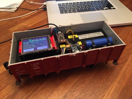
Hey, I purchased a few 2.8" Touch Screens to use as the display/user interface for a recent hobby project.. (My first exploration of using a touchscreen device for input! Fun, fun!)


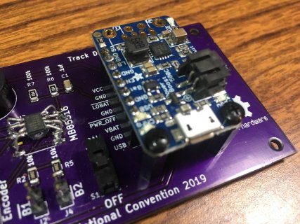
I also poked at OSH Park and ordered a few of the Purple Test Boards, and while they work great for my prototype, I'd like to spin my own version, or at least try..
So, "the question": Can I have access to the KiCAD or Eagle files for the Purple Test Board as a starting point to add in my own bit of fun? I couldn't find any obvious link to source files for this board.. Uh, I suppose I should sift Paul's GIThub page? (DOH!!)
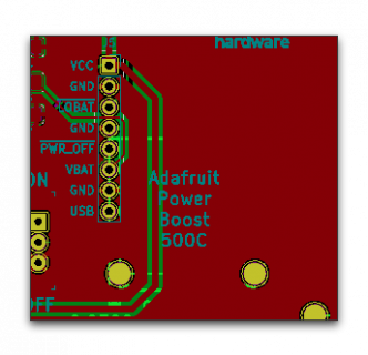
I want to alter the power input, add a header for an Adafruit Power Boost 500C and a SPI FRAM memory chip as well as another header for the encoder input.. Currently I'm hacking a "go between" protoboard along with too many custom wires, and while that all works just fine, it's simply too labor intensive to produce more than the initial concept prototype - seems like a custom "mother board" for my project would be simpler and easier, especially if I end up making more than one or two..
Anyway, I suppose I could start from scratch, but perhaps easier to leverage off of others work? (like most of my "creative work") ;-)
Thanks so much for your time - no hurry..
Sincerely,
Eric Timberlake
(a pseudo nerd of weak C++-foo, or eagle-foo, for that matter.. No kiCAD-foo at all!! No time like the present to learn something new!)
Hey, I purchased a few 2.8" Touch Screens to use as the display/user interface for a recent hobby project.. (My first exploration of using a touchscreen device for input! Fun, fun!)


I also poked at OSH Park and ordered a few of the Purple Test Boards, and while they work great for my prototype, I'd like to spin my own version, or at least try..
So, "the question": Can I have access to the KiCAD or Eagle files for the Purple Test Board as a starting point to add in my own bit of fun? I couldn't find any obvious link to source files for this board.. Uh, I suppose I should sift Paul's GIThub page? (DOH!!)
I want to alter the power input, add a header for an Adafruit Power Boost 500C and a SPI FRAM memory chip as well as another header for the encoder input.. Currently I'm hacking a "go between" protoboard along with too many custom wires, and while that all works just fine, it's simply too labor intensive to produce more than the initial concept prototype - seems like a custom "mother board" for my project would be simpler and easier, especially if I end up making more than one or two..
Anyway, I suppose I could start from scratch, but perhaps easier to leverage off of others work? (like most of my "creative work") ;-)
Thanks so much for your time - no hurry..
Sincerely,
Eric Timberlake
(a pseudo nerd of weak C++-foo, or eagle-foo, for that matter.. No kiCAD-foo at all!! No time like the present to learn something new!)


