My dear friends,
I don't have any technical background, nor had I programming lessons. Three years ago I started with a few Arduino projects that are still up and running. I was so impressed by it that I wanted to prepare my own PCB that leaves as many future connections open as possible. For this reason I decided last year to go a step further with Teensy 3.5 in a compact format.
After I shorted the first Teensy 3.5 by mixing up the Ethernet connections (as they are up side down) of VCC and GND I corrected my PCB layout and gave it another try (as the pins of the Teensy are not breadboard friendly I could only try out some functions one after another before).
While building the second layout step by step I have had success powering the board up with different smaller sketches - however that didn't last long - for the second time I shorted the Teensy: my multimeter shows that VCC and GND are connected again. This damn thing was successfully running several times with different sketches to test some connected boards as the INA219/W5500 Ethernet Module/sensors and without any further changes it broke?! I've read in another thread that "high capacitors" might cause this problem, but what on earth means "high"? Most of the capacitors on my PCB stabilize the power output of three LM1117s (2x 3V3 + 1x5V for Teensy). The board will be powered by a 24V solar bank (voltage ranges between 24 and 29V), for this reason the DC-DC Buck Converter on the bottom of the PCB reduces the voltage to around 11 volts for those mentioned LM1117s. It also worked successfully with my lab power supply. Most of the connections shown are simple terminal connectors for future purposes:
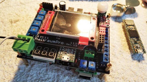
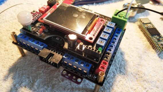
Top front view with voltmeter on the left, motion sensor and ST7735 Display
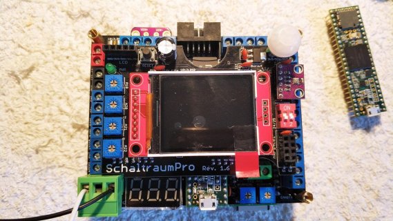
Top view with socket for future nRF24L01 module and pressure sensor on the right
Top back view with INA219 current sensor on the bottom
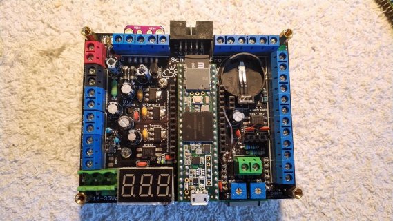
Top view of the main PCB
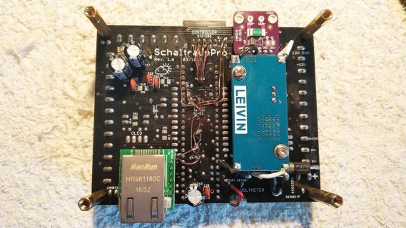
Bottom view with DC-DC buck converter and W5500 Ethernet Module (with 2x 220uF capacitors for it). None of the enamelled copper wire from the bottom of the Teensy has a short.
Right now I have to decided wherever I want to risk a third board or go back to Arduino which never fried so far. As my knowledge is limited I am willing to pay somebody that can help me with a hardware and software set-up to get at least started in a save way! In this very moment I don't know if I should throw everything away as this task exceeds my capacity, on the other hand this project for my parents is a heartfelt wish for which I already invested quite a lot of patience and time! Of course I can deliver complete EAGLE files or PDFs of the schematic.
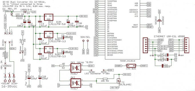
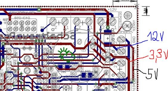
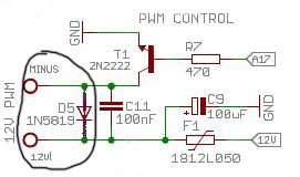
Power for the whole PCB
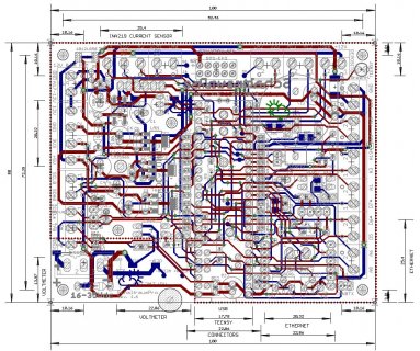
PCB just for reference
What I primarily intend to do with this board is:
1. Measure the water flow of a garden hose as an interrupt over 24 and 48 hours
2. Measure the rain (rain bucket) as an interrupt over 24 and 48 hours
3. Read two numbers of a website with the Ethernet module and show the measurements (of 1. and 2.) on a simple website
4. Show measurements on an 1.8" Adafruit ST7735 Display
5. Save measurements on SD card
Later on I would like to add some temperature sensors and relays.
I will exclaim in delight if someone has an idea why the Teensy friend again or if an expert than can help out. Thank you!
I don't have any technical background, nor had I programming lessons. Three years ago I started with a few Arduino projects that are still up and running. I was so impressed by it that I wanted to prepare my own PCB that leaves as many future connections open as possible. For this reason I decided last year to go a step further with Teensy 3.5 in a compact format.
After I shorted the first Teensy 3.5 by mixing up the Ethernet connections (as they are up side down) of VCC and GND I corrected my PCB layout and gave it another try (as the pins of the Teensy are not breadboard friendly I could only try out some functions one after another before).
While building the second layout step by step I have had success powering the board up with different smaller sketches - however that didn't last long - for the second time I shorted the Teensy: my multimeter shows that VCC and GND are connected again. This damn thing was successfully running several times with different sketches to test some connected boards as the INA219/W5500 Ethernet Module/sensors and without any further changes it broke?! I've read in another thread that "high capacitors" might cause this problem, but what on earth means "high"? Most of the capacitors on my PCB stabilize the power output of three LM1117s (2x 3V3 + 1x5V for Teensy). The board will be powered by a 24V solar bank (voltage ranges between 24 and 29V), for this reason the DC-DC Buck Converter on the bottom of the PCB reduces the voltage to around 11 volts for those mentioned LM1117s. It also worked successfully with my lab power supply. Most of the connections shown are simple terminal connectors for future purposes:

Top front view with voltmeter on the left, motion sensor and ST7735 Display

Top view with socket for future nRF24L01 module and pressure sensor on the right

Top back view with INA219 current sensor on the bottom

Top view of the main PCB

Bottom view with DC-DC buck converter and W5500 Ethernet Module (with 2x 220uF capacitors for it). None of the enamelled copper wire from the bottom of the Teensy has a short.
Right now I have to decided wherever I want to risk a third board or go back to Arduino which never fried so far. As my knowledge is limited I am willing to pay somebody that can help me with a hardware and software set-up to get at least started in a save way! In this very moment I don't know if I should throw everything away as this task exceeds my capacity, on the other hand this project for my parents is a heartfelt wish for which I already invested quite a lot of patience and time! Of course I can deliver complete EAGLE files or PDFs of the schematic.

Power for the whole PCB

PCB just for reference
What I primarily intend to do with this board is:
1. Measure the water flow of a garden hose as an interrupt over 24 and 48 hours
2. Measure the rain (rain bucket) as an interrupt over 24 and 48 hours
3. Read two numbers of a website with the Ethernet module and show the measurements (of 1. and 2.) on a simple website
4. Show measurements on an 1.8" Adafruit ST7735 Display
5. Save measurements on SD card
Later on I would like to add some temperature sensors and relays.
I will exclaim in delight if someone has an idea why the Teensy friend again or if an expert than can help out. Thank you!


