How to run PWM output for predefined number of pulses?

Status
Not open for further replies.

BenLewis

Member
I need to run a PWM output for a predefined number of pulses. The frequency is generally around 50 Hz. The duty cycle can be anywhere form 0 to 100 %.

I'm currently using the Teensy pulsed output (https://www.pjrc.com/teensy/td_pulse.html) functionally to generate a PWM output. This is working well.

My current plan is to use the FreqMeasureMulti (https://github.com/PaulStoffregen/FreqMeasureMulti) library to detect and count pulses (on the falling edge) and then disable the PWM output after a set number of pulses. I think this will work except when the duty cycle is high and an extra pulse may be generated before the previous pulse is detected. Is there an alternative solution?
 
My current plan is to use the FreqMeasureMulti (https://github.com/PaulStoffregen/FreqMeasureMulti) library to detect and count pulses (on the falling edge) and then disable the PWM output after a set number of pulses. I think this will work except when the duty cycle is high and an extra pulse may be generated before the previous pulse is detected. Is there an alternative solution?

This, or just attachInterrupt() with a wire connecting the pulse output to another pin used as an input, should work.
 
Can't the FTM channel be configured to automatically launch an interrupt per PWM cycle? In that case, counting pulses would be very easy.
 
I like the idea of triggering the counts off the FTM, but so far I can't get this to work.

I think the problem might be due to the analogWrite() function using the same interrupt.

Here is my code.

Code:
int pin_pwm = 23; //LED pin
uint32_t duty = 9830; // 15% duty
uint32_t ftm0_isr_cnt = 0;
uint32_t time_millis = 0;
uint32_t time_print = 0;
uint32_t time_print_prev = 0;
float freq = 50.0;

void ftm0_isr(void) {
  FTM0_C7SC &= ~FTM_CSC_CHF; // clear channel interrupt flag (CHF)
  ftm0_isr_cnt++;
}

void setup() {
  Serial.begin(115200);
  analogWriteFrequency(pin_pwm, freq);
  analogWriteResolution(16);
  analogWrite(pin_pwm, duty);
  FTM0_MODE = FTM_MODE_WPDIS; // enable write
  FTM0_C7SC |= FTM_CSC_CHF; // Enable interupts
  FTM0_C7SC &= ~FTM_CSC_ELSB; // Rising edge
  FTM0_C7SC |= FTM_CSC_ELSA; // Rising edge
  NVIC_ENABLE_IRQ(IRQ_FTM0);
}

void loop() {
  time_millis = millis();
  time_print = time_millis - time_print_prev;
  if (time_print >= 1000) {
    Serial.print("FTM0_C7SC: ");
    Serial.print(FTM0_C7SC, BIN);
    Serial.print(", ftm0_isr_cnt: ");
    Serial.println(ftm0_isr_cnt);
    time_print_prev = time_millis;
  }
}

And here is the output.
Code:
FTM0_C7SC: 100100, ftm0_isr_cnt: 0
...

Any suggestions to get me on the right track would be very much appreciated.
 
try this (you need volatile for variables being updated in ISR)
Code:
// teensy 3 FTM timer  FTM0_CH1_PIN 23
volatile unsigned long ticks;

void ftm0_isr(void) {
  FTM0_SC &= ~FTM_SC_TOF;  // reset interrupt
  ticks++;
}

void setup() {
  Serial.begin(9600);
  while (!Serial);
  NVIC_ENABLE_IRQ(IRQ_FTM0);
  FTM0_SC = FTM_SC_CLKS(1) | FTM_SC_PS(0) | FTM_SC_TOF | FTM_SC_TOIE;
  analogWrite(23, 128);
}

void loop() {
  Serial.println(ticks);
  delay(1000);
}
tested on T3.2. interrupts on rising edge of PWM.
 
Last edited:
I'm now able to count PWM pulses and stop the PWM output after a predefined number of pulses. However, on the first run after boot the number of pulses output is always one less than required.

The following code is intended to output one pulse after each new message is received over the serial port.

Code:
#define CS_BITMASK 0x18

int pin_pwm = 23; //LED pin
uint32_t duty = 9830; // 15% duty
volatile unsigned int ftm0_isr_cnt = 0;
unsigned int cnt = 1;
bool newData = false;

void ftm0_isr(void) {
  FTM0_SC &= ~FTM_SC_TOF; // reset interrupt
  if (ftm0_isr_cnt < cnt) {
    ftm0_isr_cnt++;
  }
  if (ftm0_isr_cnt == cnt) {
    FTM0_SC = (FTM0_SC & ~CS_BITMASK) | FTM_SC_CLKS(0);
  }
}

void setup() {
  Serial.begin(115200);
  analogWriteFrequency(pin_pwm, 50); // 50 Hz
  analogWriteResolution(16);
  FTM0_SC = (FTM0_SC & ~CS_BITMASK) | FTM_SC_CLKS(0); // Disable timer
  analogWrite(pin_pwm, 9830);  // 15% duty
  FTM0_SC |= FTM_SC_TOIE; // Enable interrupt
  NVIC_ENABLE_IRQ(IRQ_FTM0);
  while (!Serial);
}

void loop() {
  while (Serial.available() > 0) {
    Serial.read();
    newData = true;
  }
  if (newData){
    ftm0_isr_cnt = 0;
    FTM0_SC = (FTM0_SC & ~CS_BITMASK) | FTM_SC_CLKS(1);  // Enable timer
    Serial.print("FTM0_SC: ");
    Serial.print(FTM0_SC, BIN);
    Serial.print(", Pulses: ");
    Serial.println(cnt);
    newData = false;
  }
}

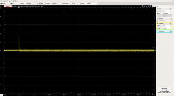
Here is the output on the first run after boot.
output1.jpg

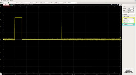
Here is the output on all subsequent runs.
output2.jpg

Here is the output on the console:
Code:
FTM0_SC: 1001101, Pulses: 1

How do I get the correct number of pulses on the first run after boot?

Tested on Teensy 3.5
 
Last edited:
Hi gfvalvo, thank you for your suggestion.

I tried clearing the TOF flag in setup() but I get the same result. That is, no pulse on first run and one pulse for every run there after.

Here is my code.

Code:
#define CS_BITMASK 0x18

int pin_pwm = 23; //LED pin
uint32_t duty = 9830; // 15% duty
volatile unsigned int ftm0_isr_cnt = 0;
unsigned int cnt = 1;
bool newData = false;

void ftm0_isr(void) {
  FTM0_SC &= ~FTM_SC_TOF; // Reset interrupt
  if (ftm0_isr_cnt < cnt) {
    ftm0_isr_cnt++;
  }
  if (ftm0_isr_cnt == cnt) {
    FTM0_SC = (FTM0_SC & ~CS_BITMASK) | FTM_SC_CLKS(0);
  }
}

void setup() {
  Serial.begin(115200);
  analogWriteFrequency(pin_pwm, 50); // 50 Hz
  analogWriteResolution(16);
  FTM0_SC = (FTM0_SC & ~CS_BITMASK) | FTM_SC_CLKS(0); // Disable timer
  analogWrite(pin_pwm, 9830);  // 15% duty
  FTM0_SC &= ~FTM_SC_TOF; // Reset interrupt
  FTM0_SC |= FTM_SC_TOIE; // Enable interrupt
  NVIC_ENABLE_IRQ(IRQ_FTM0);
  while (!Serial);
}

void loop() {
  while (Serial.available() > 0) {
    Serial.read();
    newData = true;
  }
  if (newData){
    ftm0_isr_cnt = 0;
    FTM0_SC = (FTM0_SC & ~CS_BITMASK) | FTM_SC_CLKS(1);  // Enable timer
    Serial.print("FTM0_SC: ");
    Serial.print(FTM0_SC, BIN);
    Serial.print(", Pulses: ");
    Serial.println(cnt);
    newData = false;
  }
}
 
This worked for me on a T3.2:
Code:
#include "Arduino.h"

uint8_t saveClockSource;
volatile bool pwmRunning = false;
volatile uint8_t numPulses = 1;
volatile uint8_t pulseCount;

void setup() {
  const uint8_t pwmPin = 22;
  Serial.begin(115200);
  delay(1000);
  Serial.println("Starting");
  pinMode(pwmPin, OUTPUT);
  digitalWrite(pwmPin, LOW);

  analogWriteFrequency(pwmPin, 50);
  analogWriteResolution(16);

  saveClockSource = FTM0_SC & FTM_SC_CLKS(3);
  FTM0_SC &= ~FTM_SC_CLKS(3);
  analogWrite(pwmPin, 9830);
  FTM0_C0SC &= ~FTM_CSC_CHIE;
  NVIC_ENABLE_IRQ(IRQ_FTM0);
}

void loop() {
  bool startPWM = false;
  char c;

  if (!pwmRunning) {
    while (Serial.available() > 0) {
      c = Serial.read();
      switch (c) {
        case 'u':
          if (numPulses < 10) {
            numPulses++;
            Serial.print("numPulses: ");
            Serial.println(numPulses);
          }
          break;

        case 'd':
          if (numPulses > 1u) {
            numPulses--;
            Serial.print("numPulses: ");
            Serial.println(numPulses);
          }
          break;

        case 'g':
          startPWM = true;
          break;

        default:
          break;
      }
    }

    if (startPWM) {
      pwmRunning = true;
      Serial.print("Sending ");
      Serial.print(numPulses);
      Serial.println(" Pulse(s)");
      pulseCount = 0;

      FTM0_C0SC &= ~FTM_CSC_CHF;
      FTM0_C0SC |= FTM_CSC_CHIE;
      FTM0_CNT = 0;
      FTM0_SC |= saveClockSource;
    }
  }
}

void ftm0_isr(void) {
  if (FTM0_C0SC & FTM_CSC_CHF) {
    FTM0_C0SC &= ~FTM_CSC_CHF;
    pulseCount++;
    if (pulseCount >= numPulses) {
      FTM0_C0SC &= ~FTM_CSC_CHIE;
      FTM0_SC &= ~FTM_SC_CLKS(3);
      pwmRunning = false;
    }
  }
}
 
Last edited:
Here’s a slightly different technique that also works. It keeps the FTM enabled the whole time and just shuts down the output channel after the requisite number of pulses have been sent. Doing it this way would allow multiple channels on the FTM to output independent pulse widths and pulse counts initiated at different times. The downside of this technique is that there may be a delay before the pulse stream starts because the channel might not start outputting pulses until then next counter rollover.
Code:
#include "Arduino.h"

const uint8_t pwmPin = 22;
uint8_t saveClockSource;
volatile bool pwmRunning = false;
volatile uint8_t numPulses = 1;
volatile uint8_t pulseCount;

void setup() {
  Serial.begin(115200);
  delay(1000);
  Serial.println("Starting");
  pinMode(pwmPin, OUTPUT);
  digitalWrite(pwmPin, LOW);

  analogWriteFrequency(pwmPin, 50);
  analogWriteResolution(16);
  FTM0_C0SC &= ~FTM_CSC_CHIE;
  NVIC_ENABLE_IRQ(IRQ_FTM0);
}

void loop() {
  bool startPWM = false;
  char c;

  if (!pwmRunning) {
    while (Serial.available() > 0) {
      c = Serial.read();
      switch (c) {
        case 'u':
          if (numPulses < 10) {
            numPulses++;
            Serial.print("numPulses: ");
            Serial.println(numPulses);
          }
          break;

        case 'd':
          if (numPulses > 1u) {
            numPulses--;
            Serial.print("numPulses: ");
            Serial.println(numPulses);
          }
          break;

        case 'g':
          startPWM = true;
          break;

        default:
          break;
      }
    }

    if (startPWM) {
      pwmRunning = true;
      Serial.print("Sending ");
      Serial.print(numPulses);
      Serial.println(" Pulse(s)");
      pulseCount = 0;

      FTM0_C0SC &= ~FTM_CSC_CHF;
      FTM0_C0SC |= FTM_CSC_CHIE;
      analogWrite(pwmPin, 9830);
    }
  }
}

void ftm0_isr(void) {
  if (FTM0_C0SC & FTM_CSC_CHF) {
    FTM0_C0SC &= ~FTM_CSC_CHF;
    pulseCount++;
    if (pulseCount >= numPulses) {
      FTM0_C0SC &= ~FTM_CSC_CHIE;
      digitalWrite(pwmPin, LOW);
      pinMode(pwmPin, OUTPUT);
      pwmRunning = false;

    }
  }
}
 
Last edited:
Hi gfvalvo, thank you for your very useful examples. They work great!

I've made just one small change to your second example. Like in your first example, the counter needs to be reset ( with FTM0_CNT = 0; ) prior to enabling the PWM output. This way the first pulse always has the correct width. Without this change the first pulse was sometimes too short.

Here is the full code:

Code:
#include "Arduino.h"

const uint8_t pwmPin = 22;
volatile bool pwmRunning = false;
volatile uint8_t numPulses = 1;
volatile uint8_t pulseCount;

void setup() {
  Serial.begin(115200);
  delay(1000);
  Serial.println("Starting");
  pinMode(pwmPin, OUTPUT);
  digitalWrite(pwmPin, LOW);

  analogWriteFrequency(pwmPin, 50);
  analogWriteResolution(16);
  FTM0_C0SC &= ~FTM_CSC_CHIE;
  NVIC_ENABLE_IRQ(IRQ_FTM0);
}

void loop() {
  bool startPWM = false;
  char c;

  if (!pwmRunning) {
    while (Serial.available() > 0) {
      c = Serial.read();
      switch (c) {
        case 'u':
          if (numPulses < 10) {
            numPulses++;
            Serial.print("numPulses: ");
            Serial.println(numPulses);
          }
          break;

        case 'd':
          if (numPulses > 1u) {
            numPulses--;
            Serial.print("numPulses: ");
            Serial.println(numPulses);
          }
          break;

        case 'g':
          startPWM = true;
          break;

        default:
          break;
      }
    }

    if (startPWM) {
      pwmRunning = true;
      Serial.print("Sending ");
      Serial.print(numPulses);
      Serial.println(" Pulse(s)");
      pulseCount = 0;

      FTM0_C0SC &= ~FTM_CSC_CHF;
      FTM0_C0SC |= FTM_CSC_CHIE;
      FTM0_CNT = 0;
      analogWrite(pwmPin, 9830);
    }
  }
}

void ftm0_isr(void) {
  if (FTM0_C0SC & FTM_CSC_CHF) {
    FTM0_C0SC &= ~FTM_CSC_CHF;
    pulseCount++;
    if (pulseCount >= numPulses) {
      FTM0_C0SC &= ~FTM_CSC_CHIE;
      digitalWrite(pwmPin, LOW);
      pinMode(pwmPin, OUTPUT);
      pwmRunning = false;
    }
  }
}

I have some questions:

* What is the purpose of the first line in the ISR?
Code:
if (FTM0_C0SC & FTM_CSC_CHF) {

* Why does this code not work on pin 23?
 
* What is the purpose of the first line in the ISR?
Code:
if (FTM0_C0SC & FTM_CSC_CHF) {

* Why does this code not work on pin 23?

pin 23 PWM is controlled by FTM0 Ch1 and pin 22 is controlled by FTM0 Ch0. To use pin 23, change all FTM0_C0SC to FTM0_C1SC

if (FTM0_C0SC & FTM_CSC_CHF) checks if the ISR was fired by FTM0_C0SC (compare match on FTM0 CH0)
 
I've made just one small change to your second example. Like in your first example, the counter needs to be reset ( with FTM0_CNT = 0; ) prior to enabling the PWM output. This way the first pulse always has the correct width. Without this change the first pulse was sometimes too short.
Yes, I realized that runt first pulses were a possibility, but did not test it enough to observe any. I just did today. The trouble with resetting the counter is that it will screw up all other PWM signals running on that FTM. An FTM can have up to 8 channels and I wanted to be able to run independent PWM signals on all of them (either continuous signals or finite-length ones like we’re implementing here).

So, I think the new code below fixes the runt pulse problem without having to reset the counter. Give it a try.

I see that @manitou has already answered your other questions.
Code:
#include "Arduino.h"

const uint8_t pwmPin = 22;
uint16_t saveFTM0_C0V;
volatile bool pwmRunning = false;
volatile uint8_t numPulses = 1;
volatile uint8_t pulseCount;

void setup() {
  uint8_t saveClockSource;

  Serial.begin(115200);
  delay(1000);
  Serial.println("Starting");
  pinMode(pwmPin, OUTPUT);
  digitalWrite(pwmPin, LOW);

  analogWriteFrequency(pwmPin, 50);
  analogWriteResolution(16);
  saveClockSource = FTM0_SC & FTM_SC_CLKS(3);
  FTM0_SC &= ~FTM_SC_CLKS(3);
  analogWrite(pwmPin, 9830);
  saveFTM0_C0V = FTM0_C0V;
  FTM0_C0V = 0;
  FTM0_SC |= saveClockSource;

  FTM0_C0SC &= ~FTM_CSC_CHIE;
  NVIC_ENABLE_IRQ(IRQ_FTM0);
}

void loop() {
  bool startPWM = false;
  char c;

  if (!pwmRunning) {
    while (Serial.available() > 0) {
      c = Serial.read();
      switch (c) {
        case 'u':
          if (numPulses < 10) {
            numPulses++;
            Serial.print("numPulses: ");
            Serial.println(numPulses);
          }
          break;

        case 'd':
          if (numPulses > 1u) {
            numPulses--;
            Serial.print("numPulses: ");
            Serial.println(numPulses);
          }
          break;

        case 'g':
          startPWM = true;
          break;

        default:
          break;
      }
    }

    if (startPWM) {
      pwmRunning = true;
      Serial.print("Sending ");
      Serial.print(numPulses);
      Serial.println(" Pulse(s)");
      pulseCount = 0;

      FTM0_C0SC &= ~FTM_CSC_CHF;
      FTM0_C0SC |= FTM_CSC_CHIE;
      FTM0_C0V = saveFTM0_C0V;
    }
  }
}

void ftm0_isr(void) {
  if (FTM0_C0SC & FTM_CSC_CHF) {
    FTM0_C0SC &= ~FTM_CSC_CHF;
    pulseCount++;
    if (pulseCount >= numPulses) {
      FTM0_C0SC &= ~FTM_CSC_CHIE;
      FTM0_C0V = 0;
      pwmRunning = false;
    }
  }
}
 
Hi gfvalvo, thank you for your latest example code. It works great! This is a very nice solution to my problem.
 
Can someone suggest how to do the same on Teensy 4.x using FlexPWM?

I have been reading the manual and it looks like one could use the E-Capture module to measure the cycles by 8-bit EDGCMP_X register (manual pg. 3060), but I don't know how to set this up.

Can the same Flexpwm submodule be used to make PWM pulses on channels A and B, and at the same time capture the rising edge of one channel by auxillary channel X? Do these pins need to be wired physically together, or can be connected in software?

Your help is much appreciated!
 
I'm using the T4's FlexPwm to drive Neopixels. They take 24 PWM pulses per led, and chain from one to the next; my current board has 6.

I set up the FlexPwm to idle low, create an array in memory (one byte per bit), and DMA the appropriate number of PWM 'bits' out. I add 0-width PWM bits at the end of the DMA so the output returns to idling low. Neopixels require 1.25 uSec pulse times, so I'm happier with DMA than trying to handle interrupts at that speed.

In your case you could sent up an array of the number of bits you want to write, and DMA/interrupt-handle just those bits. It seems clumsy to try to count bits when you can just write the proper number of bits. See Theremingenieur's point above.


Or am I missing something?
 
My application is a bit different; it requires constant stream of pulses with constant pulse wdith and varying frequency, up to 200kHz (think stepper motor). At at external request with period of 1ms+/-10us, I would like to provide the information how many cycles have been already done.
I reckon this would be possible by using the EDGCMP registers of the eCapture module, and at 200kHz, 8 bit should even be enough and no interrupt handling would be required (except the one at overflow).

Your solution would DMA might be also very useful though. Do you mind sharing some code?
 
I've plopped my current code to githib here. You'll be interested in LedServices.h and LedServices.cpp

My application requires constant frequency, with variations in the "High" times. It seems that your application wants constant pulse width with varying intervals? There's enough capability in the T4 FlexPWM architecture to support almost anything.

For an output frequency of 200kHz I'd certainly use DMA. Regarding your statistics gathering, I'd use an IntervalTimer if I was doing the timing, or allow volatile access to the code driving the DMA if some other mechanism is gathering the statistics. You *could* count pulses, but it seems to be a lot of trouble if you're the one generating the pulses. OTOH, you'd get "independent confirmation"; it's your call!

<Edit>It just occurred to me: If you're only changing the frequency every 1ms, you could just set the output frequency every 1ms and compute the number of pulses you'll emit...
 
Status
Not open for further replies.
Back
Top