ILI9488_t3 - Support for the ILI9488 on T3.x and beyond...

Whenever I change the spi clock, something changes in the configuration. Is that normal?

20:04:34.989 -> HX8357 Test!
20:04:34.989 -> _t3n::begin mosi:11 miso:12 SCLK:13 CS:10 DC:9 SPI clocks: 20000000 2000000
20:04:34.989 -> T4 setup CS/DC
20:04:35.601 -> _t3n::begin - completed
20:04:35.695 -> Display Power Mode: 0x80
20:04:35.695 -> MADCTL Mode: 0x0
20:04:35.695 -> Pixel Format: 0x87
20:04:35.695 -> Image Format: 0x87
20:04:35.695 -> Self Diagnostic: 0x87
20:04:35.695 -> Benchmark Time (microseconds)
20:04:35.695 -> Screen fill 615109
20:04:36.526 -> Text 126456
20:04:37.374 -> Lines 187222
20:04:38.817 -> Horiz/Vert Lines 50861
20:04:39.194 -> Rectangles (outline) 28441
20:04:39.523 -> Rectangles (filled) 1486488
20:04:41.354 -> Circles (filled) 193503
20:04:41.682 -> Circles (outline) 152359
20:04:42.060 -> Triangles (outline) 39841
20:04:42.390 -> Triangles (filled) 491160
20:04:43.275 -> Rounded rects (outline) 62436
20:04:43.651 -> Rounded rects (filled) 1622392
20:04:45.575 -> Done!
 
I will try running one of them.

But in all cases like this, I would also look for a reset pin on your display. Many cheap ones let these float, so if they are not connected or the like nothing works.
I see in DEV_Config.h it is pin 8 by default...

Try making sure you have one defined and it is connected the the Reset signal of your display
 
I connected the reset pin of the display to PIN 15 from Teensy. Unfortunately pin 8 is occupied. Of course I defined the pin: #define TFT_RST 15
Unfortunately I don't know how to find out if the pin on the display is really connected to it.

Edit: Reset seems to work.
20:43:25.080 -> HX8357 Test!
20:43:25.080 -> _t3n::begin mosi:11 miso:12 SCLK:13 CS:10 DC:9 SPI clocks: 30000000 2000000
20:43:25.080 -> T4 setup CS/DC
20:43:25.671 -> _t3n::begin - completed
20:43:25.766 -> Display Power Mode: 0x80
20:43:25.766 -> MADCTL Mode: 0x80
20:43:25.766 -> Pixel Format: 0x87
20:43:25.766 -> Image Format: 0x87
20:43:25.766 -> Self Diagnostic: 0x87
20:43:25.766 ->
20:43:25.766 -> Reset Display
20:43:25.766 ->
20:43:25.907 -> After Reset Display:
20:43:25.907 -> Display Power Mode: 0x80
20:43:25.907 -> MADCTL Mode: 0x80
20:43:25.907 -> Pixel Format: 0x87
20:43:25.907 -> Image Format: 0x3
20:43:25.907 -> Self Diagnostic: 0x87
20:43:25.907 -> Done!
 
Another question: I need a 4 inch display that works with the Teensy 4.0. Do you have a tip? SPI would be desirable.
Thanks
 
Again first try running the wave share software with this and see if it works.

Also If I look at pictures of your module, I am assuming that you changed the dip switches on the display to use SPI pins on 11-13 and not use the ICSP pins?


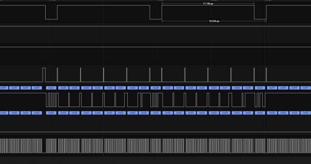
It will be interesting to see how different this controller is. I do have their example outputting on T4, looking at its outputs on Logic Analyzer. And I am wondering if some of the basics are different. Example how to output the bounds for writing data to a rectangle.

Example:
screenshot.jpg
It shows like: 0x2a 0 0 0 0 0 1 0 df 0x2b ...
It is like the min/max values are 4 bytes each but only probably lower byte of each 0-1df would be my guess.
 
Also If I look at pictures of your module, I am assuming that you changed the dip switches on the display to use SPI pins on 11-13 and not use the ICSP pins?
Yes i did.

I will try the wave share software again

Looks crazy what you're doing. :D
 
I will try the wave share software again

The program (Waveshare GraphicsTest) outputs information via serial monitor. The display remains white.

21:16:33.194 -> Benchmark Time (microseconds)
21:16:33.194 -> Screen fill 798811
21:16:34.501 -> Text 29693
21:16:37.700 -> Lines 623475
21:16:41.316 -> Rectangles (outline) 37110
21:16:42.014 -> Rectangles (filled) 1947188
21:16:44.635 -> Circles (filled) 225063
21:16:45.010 -> Circles (outline) 267299
21:16:45.803 -> Done!
21:16:45.803 -> 3928639
 
Note: I could be completely off here, but some of their stuff looks WRONG...

In particular: look at LCD_Driver.cpp at the function

Code:
void LCD_WriteData(uint8_t Data)
{
    LCD_DC_1;
    LCD_CS_0;
    SPI4W_Write_Byte(Data >> 8);
    SPI4W_Write_Byte(Data & 0XFF);
    LCD_CS_1;
}
You pass in a byte so the firsrt write will always be 0... followed by the real bytes...
what happens if you get rid of that first write?
Code:
void LCD_WriteData(uint8_t Data)
{
    LCD_DC_1;
    LCD_CS_0;
    SPI4W_Write_Byte(Data);
    LCD_CS_1;
}

Again this is their library. So again make sure your CS, DC, SPI... RESET all match the pin numbers in their config file
 
Note: I could be completely off here, but some of their stuff looks WRONG...

In particular: look at LCD_Driver.cpp at the function

Code:
void LCD_WriteData(uint8_t Data)
{
    LCD_DC_1;
    LCD_CS_0;
    SPI4W_Write_Byte(Data >> 8);
    SPI4W_Write_Byte(Data & 0XFF);
    LCD_CS_1;
}

KurtE -- while their driver leaves a lot to be desired, in this particular case I don't think LCD_WriteData() is actually wrong. Inefficient and inconsistent, perhaps! :) LCD_WriteData() is generally used for 8bit ILI9486 register accesses via a 16-bit 8080 (parallel) interface, so that function is just zero-padding the bus. It would have been clearer if they had deliberately shown a MSB forced to 0x00, rather than copying & pasting the same half-word SPI code used elsewhere. To perform the actual 16-bit RGB565 SPI accesses, the full 16-bit data is generally driven by the LCD_Write_AllData() API, which does indeed accept a uint16_t.

BTW, the "Waveshare_ILI9486" library was just my quick GFX-style wrapper upon the official driver. MHotchin has provided an alternate rewrite that is more efficient & GFX-API complete (I have proposed merging the libs & retain his updates to avoid confusion).
 
But again have you tried the changes I suggested to see if anything shows up using the Teensy?

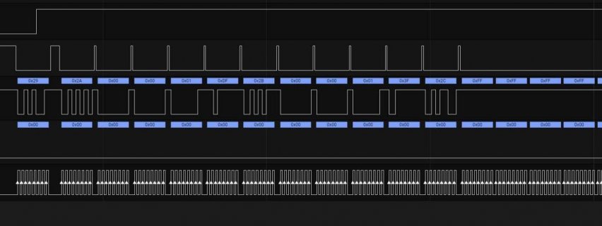
Again why I asked was if you look back a few postings to #605 you will see the Logic analyzer output, which if you remember I mentioned looked wrong! With that change it looks more like:
screenshot.jpg

Now you see the: 2a followed by 4 bytes (2 bytes for x Start, 2 bytes for x end) followed by 0x2b again 4 bytes (y start, y end) followed by 2c (write memory)...
This is the same as I see for ILI9488, ILI9341, H8357, ST7789. ST7735 is similar except as both directions are less than 256, the X and Y coordinates are one byte each...

And note from the sources, I suspected this when you look at the code that outputs it:
Code:
void LCD_SetWindow(POINT Xstart, POINT Ystart,	POINT Xend, POINT Yend)
{
    //set the X coordinates
    LCD_WriteReg(0x2A);
    LCD_WriteData(Xstart >> 8);	 				//Set the horizontal starting point to the high octet
    LCD_WriteData(Xstart & 0xff);	 				//Set the horizontal starting point to the low octet
    LCD_WriteData((Xend - 1) >> 8);	//Set the horizontal end to the high octet
    LCD_WriteData((Xend - 1) & 0xff);	//Set the horizontal end to the low octet

    //set the Y coordinates
    LCD_WriteReg(0x2B);
    LCD_WriteData(Ystart >> 8);
    LCD_WriteData(Ystart & 0xff );
    LCD_WriteData((Yend - 1) >> 8);
    LCD_WriteData((Yend - 1) & 0xff);
    LCD_WriteReg(0x2C);
}
 
But again have you tried the changes I suggested to see if anything shows up using the Teensy?

Yes, now i did. I tested the "ImpulseAdventure / Waveshare_ILI9486" lib with the Teensy.
Before that, I adjusted the pins in DEV_Config.
Code:
//LCD
#define LCD_CS 10
#define LCD_CS_0        digitalWrite(LCD_CS, LOW)
#define LCD_CS_1        digitalWrite(LCD_CS, HIGH)

#define LCD_BL 16

#define LCD_RST 15
#define LCD_RST_0       digitalWrite(LCD_RST, LOW)
#define LCD_RST_1       digitalWrite(LCD_RST, HIGH)

#define LCD_DC 9
#define LCD_DC_0        digitalWrite(LCD_DC, LOW)
#define LCD_DC_1        digitalWrite(LCD_DC, HIGH)

The display remains white. The code is running

Edit: Same with
Code:
void LCD_WriteData(uint8_t Data)
{
    LCD_DC_1;
    LCD_CS_0;
    SPI4W_Write_Byte(Data);
    // SPI4W_Write_Byte(Data >> 8);
    // SPI4W_Write_Byte(Data & 0XFF);
    LCD_CS_1;
}
 
Last edited:
Sorry, not sure what else definitive to try at this point.

Again sort of drawing at straws. For example how is your backlight setup? It appears like it is setup to do PWM on pin 9 by default. And at least looking at output on Arduino mega it has a duty cycle of about 40% Again I believe you said you connected it through resistor. So probably not issue, but...

I would probably experiment with adding more delays in the init code.
Example in the LCD_InitReg, what happens if you add something like a delay(1) after each command group:

Code:
    LCD_WriteReg(0XF9);
    LCD_WriteData(0x00);
    LCD_WriteData(0x08);
    delay(1);

    LCD_WriteReg(0xC0);
    LCD_WriteData(0x19);//VREG1OUT POSITIVE
    LCD_WriteData(0x1a);//VREG2OUT NEGATIVE
    delay(1);

    LCD_WriteReg(0xC1);
    LCD_WriteData(0x45);//VGH,VGL    VGH>=14V.
    LCD_WriteData(0x00);
    delay(1);

...
Maybe also in a few places in the LCD_Init method which calls the initReg... It already has some delays,
but maybe it needs another delay after the turn on display call...

Again the issue could be that the timings are way different
 
Hi there

a good idea with the delays but unfortunately it doesn't work.

Today I had the idea to connect an ili9341. Without changes to the code or lib. Lo and behold, the display shows at least reaction. Of course, the configuration and the resolution are not correct, but it reacts continuously. I don't get anything from the ili9486, just white.
I'd say it's broken if it wouldn't work with the mega 100% ...
PS: I also tried the ICSP header on the ili9486 board a few days ago with the toggle switches. Because these are used on the mega. Of course it didn't work either.

I will now take a closer look at the ili9486 board. I suspect the trap is there.
 
Is it a problem that I have not connected CS from the Touch and CS from the SD card?
Because, of course, SD card, touch and display are connected to the same MISO and MOSI. However, I only use the display for testing.
Maybe the shift registers cannot work without the CS of the other two?
 
Yes, the CS line must be properly driven high to silence devices on the common bus and pulled low to actually communicate to a single selected device. If those lines are floating either or both could be ignoring or talking uncontrollably if not properly controlled on each transaction.

This link has some details that may help: pjrc.com/better-spi-bus-design-in-3-steps/
 
Okay thanks. I have already installed a pullup. Not working.

But graphicstest output changes to
10:39:43.406 -> ILI9488_t3n: (T4) SPI automatically selected
10:39:43.406 ->
10:39:43.406 -> MOSI:11 MISO:12 SCK:13
10:39:43.406 -> ILI9488 Test!
10:39:43.406 -> Display Power Mode: 0xFF
10:39:43.406 -> MADCTL Mode: 0xFF
10:39:43.406 -> Pixel Format: 0xFF
10:39:43.406 -> Image Format: 0xFF
10:39:43.406 -> Self Diagnostic: 0xFF
 
Last edited:
Again why I asked was if you look back a few postings to #605 you will see the Logic analyzer output, which if you remember I mentioned looked wrong! With that change it looks more like:
View attachment 19421

Now you see the: 2a followed by 4 bytes (2 bytes for x Start, 2 bytes for x end) followed by 0x2b again 4 bytes (y start, y end) followed by 2c (write memory)...
This is the same as I see for ILI9488, ILI9341, H8357, ST7789. ST7735 is similar except as both directions are less than 256, the X and Y coordinates are one byte each...

The use of the pair of 74HC4094 shift registers to emulate a SPI interface on the 8080-16 wired ILI9486 makes things interesting. Without access to the full schematic (in particular the wiring involving WRX & SCLK at the ILI9486 interface) it’s hard to confirm, but my thought was that your proposed change may indeed still shift & present the same values into D[7:0] as in the original code but I wasn’t confident yet that we’d see WRX latch at the same time as with the original code.

As you said, there’s no substitute for trying it out on the hardware :) I should have access to the Waveshare & T4 on Monday evening and so may be able to take a look later if there was still any interest (though perhaps less so now that sep89117 has indicated concerns over his particular module).

Thanks again KurtE for sharing your ideas on the setup
 
I am sure that the display is broken. It was suddenly white and flickered slightly. I tried everything to get it back ...
If it helps you, I can tell you the imprint on the registers.
 
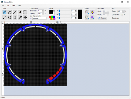
Hello everybody!
Coincidentally, is anyone interested in an image editing program that can import from C as well as export to C? So it specializes in graphics creation for Arduino based systems.
I have been working on it for a few days now and would be happy to find beta testers :)
It is written with C# .NET in Visual Studio. I can of course provide the source code and also a compiled executable for Windows.
Capture 2020-03-25 170049.png
I also developed a new type of Exprt to C. With simple bitmaps (many pixels with the same color) it can save up to 99% memory (bitmaps like the one in the picture as an example). It is rather unsuitable for images with color gradients or strong noise.

I am looking forward to your feedback
 
What I do with images, is to save them in png/jpg/etc from Photoshop and have a command line tool to convert the file to .h in given format.
 
Hello, after reading through most of this post, i thought i would give this library a shot.

I have several ili9488 displays, some from buy display and others from e-bay.

First i loaded the main library folder into the teensy specific library folder, then i tried the standard arduino libraries folder, then both.


I have tried setting several of the example scetches to either T3.2, T3.6 and T4, but every time i compile an example i get the following error :

Any thoughts?

Thanks.


Arduino: 1.8.12 (Windows 10), TD: 1.51-beta1, Board: "Teensy 4.0, Serial, 600 MHz, Faster, US English"

C:\Users\joey1\Documents\Arduino\libraries\ILI9488_t3\src\ILI9488_t3.cpp: In member function 'void ILI9488_t3::process_dma_interrupt()':

C:\Users\joey1\Documents\Arduino\libraries\ILI9488_t3\src\ILI9488_t3.cpp:4376:22: error: incompatible types in assignment of 'int' to 'ILI9488_t3* [3]'

_dmaActiveDisplay = 0; // We don't have a display active any more...

^

Multiple libraries were found for "Adafruit_GFX.h"
Used: C:\Program Files (x86)\Arduino\hardware\teensy\avr\libraries\Adafruit_GFX
Not used: C:\Users\joey1\Documents\Arduino\libraries\Adafruit_GFX_Library
Multiple libraries were found for "ili9488_t3_font_Arial.h"
Used: C:\Users\joey1\Documents\Arduino\libraries\ILI9488_t3
Not used: C:\Program Files (x86)\Arduino\hardware\teensy\avr\libraries\ILI9488_t3
Error compiling for board Teensy 4.0.

This report would have more information with
"Show verbose output during compilation"
option enabled in File -> Preferences.
 
First i loaded the main library folder into the teensy specific library folder, then i tried the standard arduino libraries folder, then both.
Not 100% sure what you mean by this but looking at the messages it looks like you have a local copy of the ILI9488_t3 lib in your Arduino libraries folder
C:\Users\joey1\Documents\Arduino\libraries\ILI9488 _t3
and a copy that was installed with Teensyduino
Code:
C:\Program Files (x86)\Arduino\hardware\teensy\avr\libraries\ILI9488_t3

For now I would recommend that you delete the version in:
Code:
C:\Program Files (x86)\Arduino\hardware\teensy\avr\libraries\ILI9488_t3
and download the latest version that is probably a few updates ahead of the Teensyduino version and replace what you have now in your Arduino libraries folder. The latest updates are at: https://github.com/mjs513/ILI9488_t3

The other thing that I can not tell from your explanation is what example are you running that is giving you the errors in your post. All you showed were the error messages. I just ran the graphics test sketch using a T4 and with no problems.
 
Back
Top