propa
Well-known member
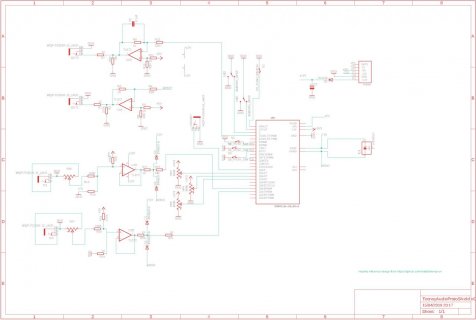
I think I'm just about to start routing this board in eagle, has a few submini toggle switches, a few nice Arcade-y D6 pushbuttons, some pots connected to analog pins and I found a teensyCV project and took a massive heap from the design using opamp's to get the inputs and outputs to the correct voltage.

I think it looks all right, but in the TeensyCV project one of the outputs of the opamps is going to the reset pin on the teensy. Is there another way to access the reset pin than that little solder pad on the board? Seems complicated to try and solder boards together, maybe I could tie a wire together from the shield to the bottom of the teensy, but it doesn't seem the most robust solution.
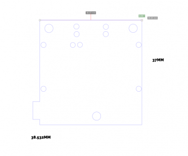
The other question before I start routing is about the layout of the audio board, are the "line ins" broken out from the chip on the audio board and only accessable via those pins on the shield? If so is there also specs on the layout of the pins on the audio board as well?
Cheers, and if you're in the uk I'd be happy to send one of the pcb's, as I'm only going to need one.


