FlexCAN_T4 - FlexCAN for Teensy 4

Regarding the method names, I think this would be better (swap the name Manual and Filter to match how you're naming the UserFilter methods):

Code:
FCTP_FUNC bool FCTP_OPT::setMBManualFilter(FLEXCAN_MAILBOX mb_num, uint32_t id1, uint32_t mask);
FCTP_FUNC bool FCTP_OPT::setFIFOManualFilter(uint8_t filter, uint32_t id1, uint32_t mask, const FLEXCAN_IDE &ide, const FLEXCAN_IDE &remote);

I think I have the setMBManualFilter working well for both STD and EXT ID mailboxes, the bit shift is incorporated into the method:

Code:
FCTP_FUNC bool FCTP_OPT::setMBManualFilter(FLEXCAN_MAILBOX mb_num, uint32_t id1, uint32_t mask) {
  if ( mb_num < mailboxOffset() || mb_num >= FLEXCANb_MAXMB_SIZE(_bus) ) return 0; /* mailbox not available */
  if ( (FLEXCAN_get_code(FLEXCANb_MBn_CS(_bus, mb_num)) >> 3) ) return 0; /* exit on TX mailbox */
  if (!(FLEXCANb_MBn_CS(_bus, mb_num) & FLEXCAN_MB_CS_IDE)) {
    mask = mask << 18;  /* shift mask by 18 for 11 bit filters */
  }
  setMBFilterProcessing(mb_num,id1,mask);
  filter_store(FLEXCAN_MULTI, mb_num, 1, id1, 0, 0, 0, 0);
  return 1;
}
 
I've got it working for FIFO:

Code:
FCTP_FUNC bool FCTP_OPT::setFIFOManualFilter(uint8_t filter, uint32_t id1, uint32_t mask, const FLEXCAN_IDE &ide, const FLEXCAN_IDE &remote) {
  if ( !(FLEXCANb_MCR(_bus) & FLEXCAN_MCR_FEN )) return 0; /* FIFO not enabled. */
  uint8_t max_fifo_filters = (((FLEXCANb_CTRL2(_bus) >> FLEXCAN_CTRL2_RFFN_BIT_NO) & 0xF) + 1) * 8; // 8->128
  if ( filter >= max_fifo_filters ) return 0;
  bool frz_flag_negate = !(FLEXCANb_MCR(_bus) & FLEXCAN_MCR_FRZ_ACK);
  FLEXCAN_EnterFreezeMode();
  /* ##################################### TABLE A ###################################### */
  if ( ((FLEXCANb_MCR(_bus) & FLEXCAN_MCR_IDAM_MASK) >> FLEXCAN_MCR_IDAM_BIT_NO) == 0 ) {
    if (ide != EXT) {
      mask = mask << 19 | 0xC0000001;
    } else {
      mask = mask << 1 | 0xC0000001;
    }
    FLEXCANb_IDFLT_TAB(_bus, filter) = ((ide == EXT ? 1 : 0) << 30) | ((remote == RTR ? 1 : 0) << 31) |
        ((ide == EXT ? ((id1 & FLEXCAN_MB_ID_EXT_MASK) << 1) : (FLEXCAN_MB_ID_IDSTD(id1) << 1)));
    if ( filter < constrain(mailboxOffset(), 0, 32) ) FLEXCANb_RXIMR(_bus, filter) = mask;// | ((filter < (max_fifo_filters / 2)) ? 0 : (1UL << 30)); // (RXIMR)
    FLEXCANb_RXFGMASK(_bus) = mask;//0x3FFFFFFF; /* enforce it for blocks 32->127, single IDs */
    fifo_filter_table[filter][0] = ( ((ide == EXT) ? 1UL : 0UL) << 16); /* extended flag check */
    fifo_filter_store(FLEXCAN_MULTI, filter, 1, id1, 0, 0, 0, 0);
  }
  /* #################################################################################### */
  /* ##################################### TABLE B ###################################### */
  if ( ((FLEXCANb_MCR(_bus) & FLEXCAN_MCR_IDAM_MASK) >> FLEXCAN_MCR_IDAM_BIT_NO) == 1 ) {
    return false;
  }

  /* #################################################################################### */
  if ( frz_flag_negate ) FLEXCAN_ExitFreezeMode();
  return 1;
}

I don't, however, understand when the method would go into Table B and I haven't been able to trigger it on any of my boards, so I just return false in that case. If there is any insight into what Table B is for, I can try to add it, but the logic was a lot more complicated than Table A.
 
Table B (or higher (gets more complex)) uses partial masking. it can do 2 full 11 bit IDs or one 11 and partial 29 bit, do NOT get me started with Table C, as that does partial QUAD ids in a 29 bit register........
If you are using your own mask, stick with Table A, it is not an easy way for people to juggle partial masking manually, although I made the library calculate it easily, doing it by hand is not the way to go unless the user has a datasheet and scrap paper to stencil on &#55357;&#56833; I have merged your current progress
 
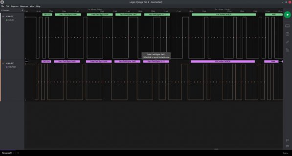
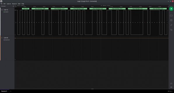
I'm still having trouble sending CAN-FD traffic from a Teensy MM while still being able to receive it perfectly fine. To aid in determining what is going on, I've taken two captures with a Saleae Logic Pro. The bad one comes from the Teensy MM and the good one comes from an ESP32 driving an MCP2517FD chip.

BadFD.jpg
That's the bad one. Here is the code I'm using to send:
Code:
    CANFD_message_t fd_out;
    fd_out.id = 0x789;
    fd_out.brs = 1; //do the baud rate switch for data section
    fd_out.edl = 1; //do extended data length too
    fd_out.len = 16;
    for (int l = 0; l < 16; l++) fd_out.buf[l] = l * 3;
    canHandlerBus2.sendFrameFD(fd_out);
The important part to note here is that I'm sending a 16 byte message. Yes, I did use setRegion(64) and can confirm that there are only 14 mailboxes. But, you can plainly see that the hardware is sending a DLC of 4 which is why I get protocol errors. It's actually sending 16 bytes of payload but since the DLC section says 4 anything trying to receive it gets very confused.

GoodFD.jpg
Here's the good one from an ESP32. The Teensy receives this just fine. You can also see that DLC is 0x10 (16) which is the correct # of bytes because that unit is also sending 16 byte messages.

So, it seems my problem is that the Teensy side sends an invalid DLC but the correct actual # of bytes thereafter. The ESP32 sends the proper bits.

Both ends are set to 500k nominal and 4M data speed. Both captures are right at the CAN-TX and CAN-RX pins of the FD transceiver on the Teensy containing board.

I have tried different clock speeds for the CAN hardware on the Teensy. Both 24 and 60MHz yield this same result. The Teensy can send standard CAN frames perfectly fine through this same interface. Both ends have FD transceivers. I've tried a lot of things and nothing really seems to resolve the fact that one side can send FD frames to the other all day but the other direction never works for FD traffic. This certainly isn't a CRC problem like I first thought. Oh, also, look at the code above. The bytes sent should be 0, 3, 6, 9 but they're coming out as 0, 6, 12, 18 which is twice the proper value each time. It appears that things are getting desynced by one bit. Could this be some sort of TDC error or propegation delay problem?

Edit: I broke out the code to a much simpler sketch (the program was otherwise extremely long and complex) and then started to toy with the speed. It seems it works fine at 500k nom, 2M data so it looks like I might have some board layout issues or something that is subtly messing up the timing at 4M. Perhaps this could still be termination related or something to do with propagation delay or something of that sort (maybe even TDC). So, I guess it seems I may have figured out my trouble.
 
Last edited:
Can you post your setup code for Teensy MM. Played with CAN FD on the Teensy MM and it works fine with FlexCAN_T4 library.
 
Troubles in paradise!

I upgraded to Arduino IDE1.8.19 and the latest Teensyduino release an I am getting the following compile errors:

Arduino: 1.8.19 (Windows 10), TD: 1.56, Board: "Teensy MicroMod, MTP Disk Serial (Experimental), 600 MHz, Faster, US English"
C:\Users\bvernham\AppData\Local\Temp\arduino_build_359038/core\core.a(WMath.cpp.o): In function `random(long, long)':

C:\Users\bvernham\Dropbox (Isuzu North America)\Personal Backup\arduino-1.8.19\hardware\teensy\avr\cores\teensy4/WMath.cpp:59: multiple definition of `random(long, long)'

C:\Users\bvernham\AppData\Local\Temp\arduino_build_359038\libraries\FlexCAN_T4\random.cpp.o:C:\Users\bvernham\Dropbox (Isuzu North America)\Personal Backup\arduino-1.8.19\hardware\teensy\avr\libraries\FlexCAN_T4/random.cpp:42: first defined here

c:/users/bvernham/dropbox (isuzu north america)/personal backup/arduino-1.8.19/hardware/tools/arm/bin/../lib/gcc/arm-none-eabi/5.4.1/../../../../arm-none-eabi/bin/ld.exe: Disabling relaxation: it will not work with multiple definitions

When I substitute a previous version of FlexCAN_T4 I do not get this error.

Was random.cpp added for some reason in the latest release?

Thank

Bruce
 
Shoot, that's my fault with the pull request that was incorporated. I thought I had done the PR off a clean version of FlexCAN_T4, only changing the filter masks to add a manual option. But I then made some more changes to my version to support CMake builds (I use both CMake and Arduino build systems), which necessitated adding my own versions of random and constrain. I'm not sure if I screwed up the PR or if GitHub kept using head instead of the commit that I meant to have incorporated.

I'll clean it up and issue another PR to fix.

Sorry, I'm more used to merges than PRs and must have screwed this one up.
 
Ok...so I got a strange one I need help with.

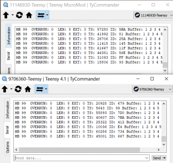
Same exact code being used between Teensy 4.1 and Micromod Teensy. I am using the same transceivers but obviously the foot print of the are differnt.

So previously I have done most of the work with the Teensy 4.1 but I have checked to make sure the code works for both.

When I checked the Micromod I typically I use the same DBC files X3 so the filtering is the same and I connect the CAN1/2/3 to the same data source.

Always see the same messaged received on CAN1/2/3. So I thought it was all good for the Micromod.

Same data for CAN1/2 being used. No issue:

Time CAN ID
0.000089 2 0x1A0
0.000098 1 0x1A0
0.000128 2 0x1B5
0.000136 1 0x1B5
0.000159 2 0x2B6
0.000168 1 0x2B6
0.000177 2 0x378
0.000185 1 0x378


Well then I tried just CAN1 on the Micromod by itself. This does not trigger the interrupt.

Same code with the Teensy 4.1 everything is all good. CAN1 by itself will trigger the interrupt.

Any thoughts on why CAN1 will trigger on Teensy 4.1 but not on the Micromod?

Thanks

Bruce
 
OK, so I went to the example "read_two_channels".

Only mod is my data is at 500K so mod the begin and as before:
CAN2 MB: 0 ID: 0x1A0 EXT: 0 LEN: 8 DATA: 249 0 0 0 0 0 0 0 TS: 32528
CAN1 MB: 0 ID: 0x1A0 EXT: 0 LEN: 8 DATA: 249 0 0 0 0 0 0 0 TS: 32534
CAN2 MB: 0 ID: 0x1B5 EXT: 0 LEN: 8 DATA: 204 1 5 144 34 32 34 32 TS: 35348
CAN1 MB: 0 ID: 0x1B5 EXT: 0 LEN: 8 DATA: 204 1 5 144 34 32 34 32 TS: 35354

CAN1/2 no problem with the micromod.

So then I comment out the CAN2 (in set up and loop) part and no messages are received.

I then commented out just the CAN2 read part on the loop and no issue. CAN1 receives and prints the messages.

So I uncommented out the CAN2 read part but set the FIFO/MB filtering to "REJECT_ALL".

CAN1 MB: 0 ID: 0x1A0 EXT: 0 LEN: 8 DATA: 249 0 0 0 0 0 0 0 TS: 2995
CAN1 MB: 0 ID: 0x1B5 EXT: 0 LEN: 8 DATA: 204 1 5 144 34 32 34 32 TS: 4641
CAN1 MB: 0 ID: 0x378 EXT: 0 LEN: 8 DATA: 16 255 255 255 255 193 255 255 TS: 7569

CAN1 receives no issue.

So I go back to the original example but disconnect CAN2 and CAN 1 receives nothing.

Reconnect CAN2 and both CAN1 and CAN2 have messages.

Why do I need CAN2 to recieve CAN1 on the Micromod but not the Teensy 4.1?
 
that sounds confusing, the processor is the same though in any case.
does the micromod follow the 1062 define specified in flexcan_t4 ?
 
From what I can see there is only Teensy4 core and the MM uses same core and mcu imxrt1062 in the board.txt file but this is different:

teensy41.build.flags.ld=-Wl,--gc-sections,--relax "-T{build.core.path}/imxrt1062_t41.ld"
teensyMM.build.flags.ld=-Wl,--gc-sections,--relax "-T{build.core.path}/imxrt1062_mm.ld"

I am not sure what impact that has on all of this.

Unfortunately this is above my knowledge level.

Thanks

Bruce
 
Ok a bit confused myself. I am using a ATP Carrier board with the TMM. Have it CAN1 and CAN2 going to a T4.1. Have the example "read_two_channels" on the TMM and the example "CAN2.0_example_FIFO_interrupts" on the T4.1.

CAN1 and CAN2 powered on:
Code:
CAN2 MB: 0  ID: 0x696  EXT: 0  LEN: 8 DATA: 1 2 3 4 5 6 7 8   TS: 50099
CAN1 MB: 0  ID: 0xE  EXT: 0  LEN: 8 DATA: 1 2 3 4 5 6 7 8   TS: 34883
CAN2 MB: 0  ID: 0xE  EXT: 0  LEN: 8 DATA: 1 2 3 4 5 6 7 8   TS: 34812
CAN2 MB: 0  ID: 0x4D5  EXT: 0  LEN: 8 DATA: 1 2 3 4 5 6 7 8   TS: 19525
CAN1 MB: 0  ID: 0x4D5  EXT: 0  LEN: 8 DATA: 1 2 3 4 5 6 7 8   TS: 19596
CAN1 MB: 0  ID: 0x5E6  EXT: 0  LEN: 8 DATA: 1 2 3 4 5 6 7 8   TS: 4309
CAN2 MB: 0  ID: 0x5E6  EXT: 0  LEN: 8 DATA: 1 2 3 4 5 6 7 8   TS: 4238

With CAN2 powered off (I pulled the power jumper):
Code:
CAN1 MB: 0  ID: 0x703  EXT: 0  LEN: 8 DATA: 1 2 3 4 5 6 7 8   TS: 61786
CAN1 MB: 0  ID: 0x192  EXT: 0  LEN: 8 DATA: 1 2 3 4 5 6 7 8   TS: 46499
CAN1 MB: 0  ID: 0x76B  EXT: 0  LEN: 8 DATA: 1 2 3 4 5 6 7 8   TS: 31212
CAN1 MB: 0  ID: 0x2DD  EXT: 0  LEN: 8 DATA: 1 2 3 4 5 6 7 8   TS: 15925
CAN1 MB: 0  ID: 0x1D3  EXT: 0  LEN: 8 DATA: 1 2 3 4 5 6 7 8   TS: 638

So I am seeing messages on CAN1 even with CAN2 unplugged. Maybe you are accidently removing power to both tranceivers.

NOTE: I have separate transceivers on CAN1 and CAN2.
 
I am not removing power to the transceiver on CAN2, I am disconnecting CAN2 from the buss.

The transceivers have the same power supply.

This is not set up with a bunch of jumpers.

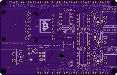
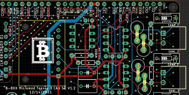
I designed a board with the transceivers to connect to the TMM with the ATP Carrier board.
TeensyMM 3CAN.jpg

Thanks
 
@bvernham
First - cool board. Was just thinking about a board like that. But anyway back to problem at hand.

When you say you are disconnecting can2 from the bus you mean you just don't have any wires connected to it, i.e., nothing connected to can2 but still powered? So if I remove the jumpers from the T4.1 to the TMM CAN2 bus and just have CAN1 connected without any CAN2 initialization you are saying its not working?

Just trying to get the right config to test with.
 
OK new test. Loaded the CAN2.0 example sketch to both TMM and the T4.1. Left CAN2 transceiver connected to the TMM but not initialized, only intialized CAN1 on the TMM. This tests both RX and TX on CAN1 only. CAN1 is working by itself on the TMM:
Capture.PNG

Only difference between sketches is I setTX(ALT) on the TMM so it transmits on Pin 11.

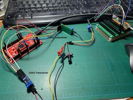
Here is a picture of my kludged setup
IMG-0608.jpg
 
Yeah, I have some weird hardware problem that has me scratching my head.

I am using the same transceivers between the T4.1 and the TMM.

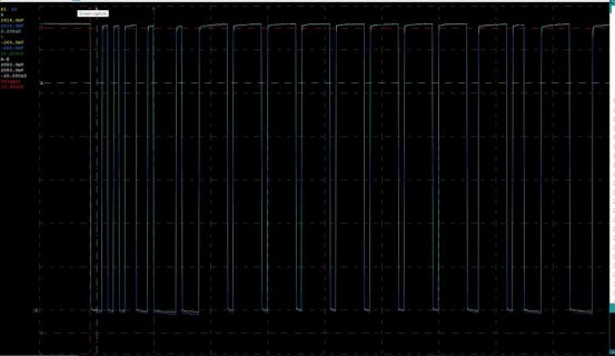
When CAN1 and CAN2 are connected together everything works as expected. This is taken from the ATP board pin.
CAN1_2 RX.jpg

Yellow is RX1 and blue is RX2.

But when I disconnect CAN2, CAN1 RX just starts going nuts.

The RX is getting pulled low even when there is no traffic so just reacting to noise for some reason.

The bus is terminated at CAN1 and CAN3 and I confirmed 60 ohms (2X120 ohm in parallel) so this one really have me scratching my head.
TMM CAN1_2.jpg

So seems like the TMM is innocent.

I even swapped transceivers and checked all of the continuities so that is not the problem.

Anyone have any ideas?

Thanks

Bruce
 
Last edited:
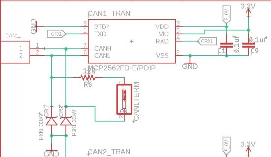
I checked and did not see any shorts or opens. Standby is tied to ground on all 3 transceivers. Using the same design as I am using with the Teensy 4.1 and same same between CAN2 and CAN3 on the board.

See schematic below.

CAN1 Transceiver.JPG

Also it is not the CANH/L side. I pulled the CAN2 and CAN3 transceivers but left the CANH/L connected as before and again, no joy!.

Blowing my mind!

Thanks
 
I checked and did not see any shorts or opens. Standby is tied to ground on all 3 transceivers. Using the same design as I am using with the Teensy 4.1 and same same between CAN2 and CAN3 on the board.

See schematic below.

View attachment 27622

Also it is not the CANH/L side. I pulled the CAN2 and CAN3 transceivers but left the CANH/L connected as before and again, no joy!.

Blowing my mind!

Thanks

I agree - should work - can't see anything that would stop it from working. Wish I could be more helpful.
 
Back
Top