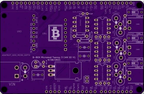
The pins are CAN3, which is what Sukkin tested. But he tested CAN FD, not CAN.
CAN2 is on the tow pins above on the ATP board he used - these are the same pins I used to confirm CAN2 is working
The pins are CAN3, which is what Sukkin tested. But he tested CAN FD, not CAN.
CAN2 is on the tow pins above on the ATP board he used - these are the same pins I used to confirm CAN2 is working
also make sure the CANRX and CANTX is not reversed?One of the unique features of the Teensy is its ability to communicate with CAN devices. The Teensy MicroMod can receive CAN messages but in order to send them properly you will need a separate CAN transceiver. CAN-RX is tied to MicroMod pad 41 (Teensy pin 30) and CAN-TX is tied to MicroMod pad 43 (Teensy pin 31).
Have you tested CAN2.0 on CAN3 controller? Can you confirm it send and receives as expected?
Yes at > 1000 frames per second (for a stress test of my code) to all 3 busses at the same time.
Great, thanks for confirming.
I put in a different Teensy MicroMod that I had in another carrier board and it worked - so it must have been a bad unit from the production line.
I have two sets right now. In on combination I do not get USB communication with one of them. If I swap the Micromod Teensy's around then everything works fine.
This is definitely a connector tolerance issue.
I have build 3 other boards with the Teensy 4.1 and work flawlessly.
Good old DIP pins never failed me.
While the DIP package is much more reliable, the form factor of the MicroMod is a winner for me.
Its small and easily replaceable!
That is why I developed both packages.
Depends if you want resident Ethernet or not.
Teensy 4.1 has 100 mbs ethernet on board also the SDIO micro SD card is a tiny more stable then having to put it on a separate board.
Distance does matter when it comes to signal integrity/timing delays and so on.
As far as I know the other micromod carrier boards use SPI not SDIO which is a waste if you are using the Teensy micromod.
So I have both ready to roll but still working on the software.
I can read DBC file and acquire/calculate both 11 and 29 but messages/signal. Send/receive PIDs including ISO TP with multiple modes (1, 9, 22) and so on.
I have GUI interface via BT 2.0 and Virtuino.
Now working on J1939 networking. Got the address claim down and working on the TP messages now.
Waiting for J1939 DBC with request messages (>8 byte messages for J1939).
I think what I have going is much more complicated that what you need to roll with.
I am handling DBC files with up to 83 messages and 400 ish signals for each buss.
I can share some ideas if you can give me some idea as to how many possible PID's you would need to be able to handle.
https://www.skpang.co.uk/
https://github.com/collin80?tab=repo...anguage=&sort=
https://github.com/stanleyhuangyc/Freematics
These are some examples of handling OBD type requests.
Hey guys,
After successfully splitting up CAN-FD frames into CAN Frames I am now at a point where I have to shift the payload of the CAN-FD payload. The reason is that I can't extract information about e.g. a velocity signal out of two seperate generated CAN Frames.
To achieve the shift I wanted to keep it simple and overwrite each buffer element of CANFD_message_t &msg struct with ist successor.
In order to avoid compile errors, I removed the "const" assignment of "CANFD_message_t &msg"Code:for (i = 1; i < msg.len; i++){ msg.buf[i] = msg.buf[i+1]; }
Awkwardly nothing changes in the payload and my outcoming CAN-Frames are not shifted.
Even more controversial is the fact, that trying following did its job:
Did I miss some special C/C++ rules regarding for loops, or do you recognize an mistake in my simple for loop?Code:msg.buf[0] = msg.buf[1];
I would be very glad if someone could help me.I am also willing to change my approach of shifting Bytes in the CAN-FD payload![]()
yes,
should be:for (i = 1; i < msg.len; i++){
msg.buf[i] = msg.buf[i+1];
}
Code:for (i = 0; i < msg.len -1; i++){ msg.buf[i] = msg.buf[i+1]; }
Hello Tonton,
May I point you to this post ?
https://forum.pjrc.com/threads/69088...-endian-format
Maybe there is already a function in your library that do "send in little-endian" ? I looked at the library and didn't find one, but I may miss it ?
If yes, can you point me to it ?
Thank you,
Manu
Hi everyone!
Why the compiler does not see templates files?Code:In file included from /Users/iuser/Desktop/CODE/sketch/config.h:19:0, from /Users/iuser/Desktop/CODE/sketch/sketch.ino:16: /Users/iuser/Desktop/CODE/sketch/src/drivers/tja1051/FlexCAN_T4.h:560:26: fatal error: FlexCAN_T4.tpp: No such file or directory #include "FlexCAN_T4.tpp" ^ compilation terminated.
Can I leave the library files where I want them or do I have to add the library to the Arduino folder?
I renaming .tpp files to _template.h and adjust the include statement accordingly.
I don't know yet if this solution will work fine. Because I don't understand how templates work at all.
For posterity - this problem occurs only in the Arduino IDE, in the PlatformIO this problem does not arise. This is due to the fact that in Arduino IDE template files cannot be located in the same folder with the sketch
it runs fine in the Arduino IDE, template (.tpp) files are supported by it, no need to rename. Even if you do rename you still need to edit the new name in the .h file to reflect that.
Hi tonton81!
It runs fine when library added to /Users/iuser/Documents/Arduino or with command add zip library file in Arduino IDE.
But in my case, the library is located in a folder on the desktop. Therefore, when you compile it, you get an error that the .TPP files is not found.
I solved this problem by renaming the TPP file to "_template.h". In the parent header file I made the necessary replacements and everything compiled.
But now I have doubts about correct workability of this variant.
workability? well if it compiles it should work because without the linkage of both files it will be impossible to compile
I'm having a similar issue with a similar board with a MAX3051 transceiver. Can't figure out why it's not working, I've tested on 2xT4.1 and 2xtransceiver boards, both on CAN1 and CAN2, TX buffers just keep filling up. Receiving end is a Pican2 Duo that I've verified is working correctly with other CAN devices. Bus termination is OK, 60 Ohm on the bus. Even tried different clock settings, but just can't seem to get it working. No receive either. Have triple checked all the wiring, should be good and checked connections even on the PCB traces that everything is hooked up as it should
Code that I've been using for testing:
Output ends up being:Code:#include <FlexCAN_T4.h> FlexCAN_T4<CAN2, RX_SIZE_256, TX_SIZE_256> Can0; void setup(void) { Serial.begin(115200); delay(400); pinMode(2, OUTPUT); digitalWrite(2, LOW); // enable tranceiver pinMode(3, OUTPUT); digitalWrite(3, LOW); // enable tranceiver delay(1000); Can0.begin(); //Can0.setClock(CLK_24MHz); Can0.setBaudRate(250000); Can0.setMaxMB(16); // up to 64 max for T4, not important in FIFO mode, unless you want to use additional mailboxes with FIFO Can0.enableFIFO(); Can0.enableFIFOInterrupt(); Can0.onReceive(canSniff); Can0.mailboxStatus(); } void canSniff(const CAN_message_t &msg) { Serial.print("MB "); Serial.print(msg.mb); Serial.print(" OVERRUN: "); Serial.print(msg.flags.overrun); Serial.print(" LEN: "); Serial.print(msg.len); Serial.print(" EXT: "); Serial.print(msg.flags.extended); Serial.print(" TS: "); Serial.print(msg.timestamp); Serial.print(" ID: "); Serial.print(msg.id, HEX); Serial.print(" Buffer: "); for ( uint8_t i = 0; i < msg.len; i++ ) { Serial.print(msg.buf[i], HEX); Serial.print(" "); } Serial.println(); } void loop() { Can0.events(); static uint32_t timeout = millis(); if ( millis() - timeout > 1000 ) { // send random frame every 20ms CAN_message_t msg; msg.id = random(0x1,0x7FE); for ( uint8_t i = 0; i < 8; i++ ) msg.buf[i] = i + 1; Can0.write(msg); timeout = millis(); Can0.mailboxStatus(); } }
Everything works OK if I use the skpang Triple CAN T4.0 board instead. Any ideas on way forward? Could it be faulty transceiver, sounds dodgy as I've tested on 2 boards, i.e. 4 different ICs. Or could it be some compatibility issue?Code:FIFO Enabled --> Interrupt Enabled FIFO Filters in use: 8 Remaining Mailboxes: 8 MB8 code: TX_DATA (Transmitting)(Standard Frame)(ID: 0x76D)(Payload: 1 2 3 4 5 6 7 8) MB9 code: TX_DATA (Transmitting)(Standard Frame)(ID: 0x4BC)(Payload: 1 2 3 4 5 6 7 8) MB10 code: TX_DATA (Transmitting)(Standard Frame)(ID: 0x489)(Payload: 1 2 3 4 5 6 7 8) MB11 code: TX_DATA (Transmitting)(Standard Frame)(ID: 0x599)(Payload: 1 2 3 4 5 6 7 8) MB12 code: TX_DATA (Transmitting)(Standard Frame)(ID: 0x151)(Payload: 1 2 3 4 5 6 7 8) MB13 code: TX_DATA (Transmitting)(Standard Frame)(ID: 0x5F2)(Payload: 1 2 3 4 5 6 7 8) MB14 code: TX_DATA (Transmitting)(Standard Frame)(ID: 0x641)(Payload: 1 2 3 4 5 6 7 8) MB15 code: TX_DATA (Transmitting)(Standard Frame)(ID: 0xC6)(Payload: 1 2 3 4 5 6 7 8)
if the TX mailboxes are all full, it is in bus off state, there is either a wiring issue to the transceiver or the device it's attached to, or the baudrate is mismatched, or a termination issue, which you said that part is correct. other than a bad baudrate, it ain't software provided the correct bus pins and bus are used
verify if the transceiver comms pins have not been crossed
It's a ready-made breakout that sits directly on T4.1 so assuming all the wiring is correct, just checked and yes, RX from Teensy going to RXD and TX to TXD for both buses, that's correct AFAIK? Tried cutting the connection between shutdown SHDN and mode-select RS pin, no difference. SHDN has a pull-down resistor, so the transceiver should stay on if the pin is disconnected.
Baudrate is the same, I tested even with 125K and 500K on both devices. Also back-to-back with 2xT4.1 setup. Running the pican2 on 250K I can plug in devices running at 250K no problem.Wiring I've tried shielded, plain wires, twisted pair etc. with no change and common GND connected between devices. Running out of options other than a bad chip?
yeah if skpang works its a physical connection/transceiver issue
on the triple can board schematic it shows CTX to TX amd CRX to RX so thats fine, and CANH to CANH and CANL to CANL, if those are still correct, you're left with the transceiver or termination at that point