Help with joystick

Status
Not open for further replies.
Hello everyone, i need your help with teensy... Please consider that i am a beginner and English is not my first language, so please have patience.

I'm trying to build an handeld console with RetroPie following some tutorials found online, just need an analog to act as a d-pad to play and scroll menus, and 8 buttons ( a b x y, left and right shoulders, start and select).
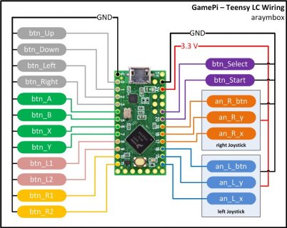

FT1JBB4JE4KS5CF.LARGE (1).jpg

I've used this diagram and it seems to work fine when I try it on windows, but as soon as i plug teensy on raspberry to configure buttons on retropie it assigns automatically the d-pad, like if some button is pressed... That's no way to make it work.

I could try to solder cables in another way, could use the teensy example for USB joystick, but cannot find any diagram for this solution... So I'm asking you guys to help me, either fixing the diagram i used or changing to the teensy example.

Thank you.
 
Here's the code, I'm using teensy 3.2


// ****************************************************************************
// Written by araym
//
// This code is in the public domain.
// ****************************************************************************


// -- Includes ----------------------------------------------------------------
#include <Bounce.h>


// -- Declare -----------------------------------------------------------------

// Digital Pad
Bounce btn_Up = Bounce( 0, 10);
Bounce btn_Down = Bounce( 1, 10);
Bounce btn_Left = Bounce( 2, 10);
Bounce btn_Right = Bounce( 3, 10);

// Action Buttons
Bounce btn_A = Bounce( 4, 10);
Bounce btn_B = Bounce( 5, 10);
Bounce btn_X = Bounce( 6, 10);
Bounce btn_Y = Bounce( 7, 10);

// Shoulder Buttons
Bounce btn_L1 = Bounce( 8, 10);
Bounce btn_L2 = Bounce( 9, 10);
Bounce btn_R1 = Bounce(10, 10);
Bounce btn_R2 = Bounce(11, 10);

// Start/Select Buttons
Bounce btn_Start = Bounce(20, 10);
Bounce btn_Select = Bounce(21, 10);

// Left Analog Stick
int an_L_x = A0;
int an_L_y = A1;
Bounce an_L_btn = Bounce(16, 10);

// Right Analog Stick
int an_R_x = A3;
int an_R_y = A4;
Bounce an_R_btn = Bounce(19, 10);


// -- Setup -------------------------------------------------------------------
void setup() {
pinMode( 0, INPUT_PULLUP); //btn_Up
pinMode( 1, INPUT_PULLUP); //btn_Down
pinMode( 2, INPUT_PULLUP); //btn_Left
pinMode( 3, INPUT_PULLUP); //btn_Right

pinMode( 4, INPUT_PULLUP); //btn_A
pinMode( 5, INPUT_PULLUP); //btn_B
pinMode( 6, INPUT_PULLUP); //btn_X
pinMode( 7, INPUT_PULLUP); //btn_Y

pinMode( 8, INPUT_PULLUP); //btn_L1
pinMode( 9, INPUT_PULLUP); //btn_L2
pinMode(10, INPUT_PULLUP); //btn_R1
pinMode(11, INPUT_PULLUP); //btn_R2

pinMode(20, INPUT_PULLUP); //btn_Start
pinMode(21, INPUT_PULLUP); //btn_Select


pinMode(A0, INPUT); //an_L_x
pinMode(A1, INPUT); //an_L_y
pinMode(16, INPUT_PULLUP); //an_L_btn

pinMode(A3, INPUT); //an_R_x
pinMode(A4, INPUT); //an_R_y
pinMode(19, INPUT_PULLUP); //an_R_btn
}


// -- Start Loop --------------------------------------------------------------
void loop() {
// Update all the buttons
btn_Up.update();
btn_Down.update();
btn_Left.update();
btn_Right.update();

btn_A.update();
btn_B.update();
btn_X.update();
btn_Y.update();

btn_L1.update();
btn_L2.update();
btn_R1.update();
btn_R2.update();

btn_Start.update();
btn_Select.update();

an_L_btn.update();
an_R_btn.update();


// Check each button for "falling" edge (= high (not pressed - voltage from pullup resistor))
if( btn_Up.fallingEdge() ) { Joystick.button( 1, 1); }
if( btn_Down.fallingEdge() ) { Joystick.button( 2, 1); }
if( btn_Left.fallingEdge() ) { Joystick.button( 3, 1); }
if( btn_Right.fallingEdge() ) { Joystick.button( 4, 1); }

if( btn_A.fallingEdge() ) { Joystick.button( 5, 1); }
if( btn_B.fallingEdge() ) { Joystick.button( 6, 1); }
if( btn_X.fallingEdge() ) { Joystick.button( 7, 1); }
if( btn_Y.fallingEdge() ) { Joystick.button( 8, 1); }

if( btn_L1.fallingEdge() ) { Joystick.button( 9, 1); }
if( btn_L2.fallingEdge() ) { Joystick.button(10, 1); }
if( btn_R1.fallingEdge() ) { Joystick.button(11, 1); }
if( btn_R2.fallingEdge() ) { Joystick.button(12, 1); }

if( btn_Start.fallingEdge() ) { Joystick.button(13, 1); }
if( btn_Select.fallingEdge() ) { Joystick.button(14, 1); }

if( an_L_btn.fallingEdge() ) { Joystick.button(15, 1); }
if( an_R_btn.fallingEdge() ) { Joystick.button(16, 1); }


// Check each button for "rising" edge (= low (pressed - button connects pin to ground))
if( btn_Up.risingEdge() ) { Joystick.button( 1, 0); }
if( btn_Down.risingEdge() ) { Joystick.button( 2, 0); }
if( btn_Left.risingEdge() ) { Joystick.button( 3, 0); }
if( btn_Right.risingEdge() ) { Joystick.button( 4, 0); }

if( btn_A.risingEdge() ) { Joystick.button( 5, 0); }
if( btn_B.risingEdge() ) { Joystick.button( 6, 0); }
if( btn_X.risingEdge() ) { Joystick.button( 7, 0); }
if( btn_Y.risingEdge() ) { Joystick.button( 8, 0); }

if( btn_L1.risingEdge() ) { Joystick.button( 9, 0); }
if( btn_L2.risingEdge() ) { Joystick.button(10, 0); }
if( btn_R1.risingEdge() ) { Joystick.button(11, 0); }
if( btn_R2.risingEdge() ) { Joystick.button(12, 0); }

if( btn_Start.risingEdge() ) { Joystick.button(13, 0); }
if( btn_Select.risingEdge() ) { Joystick.button(14, 0); }

if( an_L_btn.risingEdge() ) { Joystick.button(15, 0); }
if( an_R_btn.risingEdge() ) { Joystick.button(16, 0); }


// Left Analog Stick
Joystick.X( analogRead( an_L_x ) );
Joystick.Y( analogRead( an_L_y ) );

// Left Right Stick
Joystick.Z( analogRead( an_R_x ) );
Joystick.Zrotate( analogRead( an_R_y ) );
}
 
There are a couple of issues here, but your main problem is probably caused by bad centering of the X/Y analog axis - you need to ensure that the values are as close to 512 when the joystick is centered for control assignment to work properly in Retropie

Here are a few more suggestions:
-You should slow down your loop - it can be as simple as adding delay(1) at the beginning of loop()
-I would recommend that you put Joystick.useManualSend(true) in setup(), and Joystick.send_now() at the end of loop()
-Since you are not using the hat, I would also add Joystick.hat(-1) in setup() to make sure it does not interfere with control assignment in Retropie
-Most arcade games already implement some form of debouncing; you can simplify the code by simply using Joystick.button(1, !digitalReadFast(0))

Marc
-
 
Alright, I understand - I'm willing to help, but I would like to understand your goal with this project.

The way I see it, you could have bought a commercial Retropie bundle, ready (or almost ready) to play. Instead you got yourself a Teensy, which tells me you are curious about how this works.
A joystick project like this is a great opportunity to learn about coding, electronics, etc.
I can help you implement the suggestions I made, or even help you rewrite the whole thing if you really want to understand how it all works.

Can you tell me more about your project? What made you choose the Teensy solution over anything else?
 
Well i just want to build stuff on my own, love the diy... I'm used to build bartops and portable consoles in cases with raspberry, but this time i wanna make a handeld, which looks more complicated to me.
I mean, I thought the hardest part would have been learning to solder, but I made it... Now i'm stuck with the code and the teensy.

I choose to follow this project because i thought the code was right and I just had to copy and paste it, and then would have been easy to make other handeld every now and then, with the same project ( and code).

And yes, i am curious by nature about how the things work, but i am an artisan and i know nothing about coding or electronics, so i feel a little bit lost and to fix this come I would need a step-by-step guide
 
Ok guys could you just at least help me with example code provided by arduino program, i just don't know where to solder the cables on the teensy...


/* Basic USB Joystick Example
Teensy becomes a USB joystick

You must select Joystick from the "Tools > USB Type" menu

Pushbuttons should be connected to digital pins 0 and 1.
Wire each button between the digital pin and ground.
Potentiometers should be connected to analog inputs 0 to 1.

This example code is in the public domain.
*/

void setup() {
pinMode(0, INPUT_PULLUP);
pinMode(1, INPUT_PULLUP);
}

void loop() {
// read analog inputs and set X-Y position
Joystick.X(analogRead(0));
Joystick.Y(analogRead(1));

// read the digital inputs and set the buttons
Joystick.button(1, digitalRead(0));
Joystick.button(2, digitalRead(1));

// a brief delay, so this runs 20 times per second
delay(50);
}
 
Have you looked at the Examples -> Teensy -> USB Joystick -> complete
example sketch?

It sort of can handle up to 16/32 buttons and 6 axis... There is a minor issue, where you probably should not define the numButtons > 12, as run into the issue like if you tried to setup to read pin 14 for the 15th button, it is also analog pin 0, which is the first axis...

The example program, assumes simple Button0 is on digital 0 pin, Button1 on 1, 2 on 2... which may be fine for many of these...

But if I were doing it for myself, I would probably setup a simple button to digital mapping table, such that I am free to use whichever pins I wish...

Something like:
Code:
   const byte button_to_pin_mapping[] = {0, 1, 2, 3, 4, 5, 6, 7, 8, 9, 10, 11, 12, 21, 22, 23};  
   const byte axis_to_analog_pin_mapping[] =  {A0, A1, A2, A3, A4, A5};

Then I would change all of the code that hard referenced specific pin numbers to instead run off of the mapping tables...

For example the code to setup the input pins to be INPUT_PULLUP, might look more like:
Code:
  for (int i=0; i<numButtons; i++) {
    [COLOR="#FF0000"]pinMode(button_to_pin_mapping[i], INPUT_PULLUP)[/COLOR];
  }
And likewise in loop:
Code:
  for (int i=0; i<numButtons; i++) {
   [COLOR="#FF0000"] if (digitalRead(button_to_pin_mapping[i])) [/COLOR]{
      // when a pin reads high, the button is not pressed
      // the pullup resistor creates the "on" signal
      allButtons[i] = 0;
    } else {
      // when a pin reads low, the button is connecting to ground.
      allButtons[i] = 1;
    }
    Joystick.button(i + 1, allButtons[i]);
  }
Also might mention I show an Analog pin mapping table as well, which might make part of that sketch look like:
Code:
void loop() {
  // read 6 analog inputs and use them for the joystick axis
  Joystick.X(analogRead(axis_to_analog_pin_mapping[0]));
  Joystick.Y(analogRead(axis_to_analog_pin_mapping[1]));
  Joystick.Z(analogRead(axis_to_analog_pin_mapping[2]));
  Joystick.Zrotate(analogRead(axis_to_analog_pin_mapping[3]));
  Joystick.sliderLeft(analogRead(axis_to_analog_pin_mapping[4]));
  Joystick.sliderRight(analogRead(axis_to_analog_pin_mapping[5]));
And likewise the Hat one...
 
Well, the code i've posted should be the teensy example for usb joystick... Since I know nothing about coding i'm just trying to understand where to solder the cables using that code, and still have to add 4 more buttons, I need 6.
 
I think your picture of TLC on first posting shows how to connect up the pins...

I think maybe the question might be what is RPI particularly doing with the data? Does it expect specific Axis data in specific locations? Likewise buttons... Is it expecting specific orders...
 
I've soldered everything like in the first Pic, but when I connect the teensy on retropie it assigns 2 or more axis of the d pad... So i need help either fixing this code or using the teensy USB joy example, adding up to 6 buttons and which pin to connect every cable
 
Yes I'm used to config retropie, you can manually assign any button of your pad right from the start... The big deal is that as soon as I plug the teensy in it assigns the dpad all by itself, without touching anything.
Dunno if it's the code or what... Then my request to use the example code provided by teensy program, but need 4 more buttons and the pins to sold them
 
I think you need someone who has retropie experience?

Have you tried running it with some other type joystick? Do you still have it available?

Again I am only guessing on some of this stuff. But if it were me, the steps I would take would probably be something like:

Have a joystick that is close to the configuration I want, and then map out what values each button creates and what axis goes to what...

For example: if you have a PS3 controller: figure out what each button (X, O, TRI, SQ, PS3, Select Start, DPAD up, down, left, right, L1, L2, L3, R1, R2, R3) generate

Likewise the four main axis for left joystick up/dwn left/right likewise for right joystick...

It has been awhile, but on Linux I used to do this using I believe the application: jstest

So I would run (probably need to install it) it with it looking at the joystick object associated with the unit you are trying to emulate... Then press buttons and figure out what values changed. example quick test on Linux machine (not RPI) and did a jstest --event /dev/input/js0 where I had a PS3 plugged in. The order of buttons I believe was something like:
Buttons: X=0, O=1,TRI, SQ, L1, R1, L2, R2, select, start, PS3, HAT UP=13, DN, Left, right
Axis: Left joystick Left/right=0, UP/DOWN=1, L2 button=2, Right joystick UP/DN=3, Left/Right=4, R2=5

Again I may have typed this in wrong, and different joystick manufactures and units (PS4 different than PS3)

So the question is, if you have code like:
Code:
// Check each button for "falling" edge (= high (not pressed - voltage from pullup resistor))
if( btn_Up.fallingEdge() ) { Joystick.button( 1, 1); }
if( btn_Down.fallingEdge() ) { Joystick.button( 2, 1); }
if( btn_Left.fallingEdge() ) { Joystick.button( 3, 1); }
if( btn_Right.fallingEdge() ) { Joystick.button( 4, 1); }

if( btn_A.fallingEdge() ) { Joystick.button( 5, 1); }
if( btn_B.fallingEdge() ) { Joystick.button( 6, 1); }
if( btn_X.fallingEdge() ) { Joystick.button( 7, 1); }
if( btn_Y.fallingEdge() ) { Joystick.button( 8, 1); }

if( btn_L1.fallingEdge() ) { Joystick.button( 9, 1); }
if( btn_L2.fallingEdge() ) { Joystick.button(10, 1); }
if( btn_R1.fallingEdge() ) { Joystick.button(11, 1); }
if( btn_R2.fallingEdge() ) { Joystick.button(12, 1); }

if( btn_Start.fallingEdge() ) { Joystick.button(13, 1); }
if( btn_Select.fallingEdge() ) { Joystick.button(14, 1); }

if( an_L_btn.fallingEdge() ) { Joystick.button(15, 1); }
if( an_R_btn.fallingEdge() ) { Joystick.button(16, 1); }
How are these mapping, to what values retropie by default is expecting...
That is if some of your buttons are automatically mapped to D-Pad buttons, will maybe figure out which ones? Is it the ones in the 13-16 range?

What if you reorder your button values, like maybe: change: if( btn_Up.fallingEdge() ) { Joystick.button( 1, 1); }
to: if( btn_Up.fallingEdge() ) { Joystick.button( 13, 1); }

Maybe off by one 14? depending on if one starts counting from 0 and other 1... Obviously if you change the fallingEdge button index you will need to change the rising edge index code as well. Also probably the other buttons as well...

But again I think you just need to experiment to figure out what you need.
 
Status
Not open for further replies.
Back
Top