Teensy 3.5 SPI/Interrupts

Status
Not open for further replies.

Batman123

New member
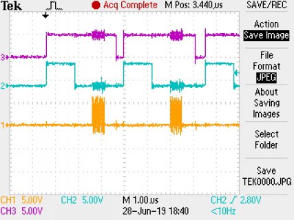
I am working with an ADC that has max sampling rate of 500kHz but using Teensy 3.5 the maximum I have been able to achieve is 300kHz. There is a ~1us delay between the data ready signal going low (blue trace) and the clock to read out the data starting (Yellow trace). Also another ~.75us delay after the clock has finished and the interrupt returns to the main loop to start the next conversion. I have attached screen capture from scope and code below. I assume there is some overhead in the beginTransaction() and endTransaction() commands, is there anyway to reduce these or is entering and exiting the interrupt likely accounting for more of the delay? I commented out the SPI.usingInterrupt() and the frequency increased by approx 20kHz.

Any help on how to reduce these delays would be much appreciated.
TEK0000.JPG

Code:
#include <SPI.h>

const int frameSize = 30000;

const byte cnv = 10;
const byte BUSY = 7;

volatile int adcBytes[frameSize];
volatile int count = 0;

volatile boolean stringComplete = false;

volatile String inputString = "";
volatile String Mode;

SPISettings settingsA(50000000, MSBFIRST, SPI_MODE0); 

void setup() 
{
  Serial.begin(250000);
  pinMode(cnv, OUTPUT);
  digitalWrite(cnv, LOW); 
  SPI.begin();
  //SPI.usingInterrupt(digitalPinToInterrupt(BUSY));
  attachInterrupt(digitalPinToInterrupt(BUSY), convers, FALLING);
}

FASTRUN void loop() 
{
      if (stringComplete)
        {
          HandleData();
        }
      
      while (Mode == "s")
        {
          digitalWrite(cnv, HIGH);  
        
          if (count == frameSize)
            {
              
              count = 0;
              for (int i=0;i<frameSize;i++)
                {
              Serial.write((adcBytes[i] >> 8) & 0xFF); // Send the upper byte first
              Serial.write(adcBytes[i] & 0xFF);            
                }
              Serial.println();
              Mode = "END";           
            }
        }
}

FASTRUN void convers()
{
SPI.beginTransaction(settingsA);
adcBytes[count] = SPI.transfer16(0);
SPI.endTransaction();
digitalWrite(cnv, LOW);
count = count+1;
}

void serialEvent()
{
  while (Serial.available())
  {
    char inChar = (char)Serial.read();
    inputString += inChar;

    if (inChar == '\n')
    {
      stringComplete = true;
    }  
  }
}

void HandleData()
{
    int commaIndex = inputString.indexOf(',');
    Mode = inputString.substring(0, commaIndex);
    inputString = "";
    stringComplete = false;
}
 
You need to remove the heavy lifting out of the ISR. With only one SPI device, you can just do SPI.beginTransaction() once. You can also use digitalWriteFast() to save a few nanoseconds. Using String variables adds overhead. I have a while(1) in loop() to avoid event-checking overhead of loop(). I have rewritten your code for my testing with a 500 KHz PWM signal (jumper pin 23 to pin 7) to indicate "data ready" for SPI. (Also most SPI devices enable transfer by pulling CS pin LOW. What is the ADC device you are using?)

Code:
#include <SPI.h>

const int frameSize = 30000;

const byte cnv = 10;
const byte BUSY = 7;

int adcBytes[frameSize];
int count = 0;
volatile int ding = 0;
uint32_t us;


SPISettings settingsA(50000000, MSBFIRST, SPI_MODE0);

void setup()
{
  Serial.begin(250000);
  pinMode(cnv, OUTPUT);
  digitalWrite(cnv, HIGH);   // SPI CS high
  SPI.begin();
  //SPI.usingInterrupt(digitalPinToInterrupt(BUSY));
  attachInterrupt(digitalPinToInterrupt(BUSY), convers, RISING);
  SPI.beginTransaction(settingsA);   // do once unless other spi devices

  analogWriteFrequency(23, 500000);
  analogWrite(23, 127); // dummy input, jumper 23 to 7
}

void loop() {
  while (1) { // avoid event checking
    if (ding) {
      digitalWriteFast(cnv, LOW);
      adcBytes[count] = SPI.transfer16(0);
      digitalWriteFast(cnv, HIGH);
      count = count + 1;
      ding = 0;
    }
    if (count >= frameSize) {
      us = micros() - us;
      Serial.printf("frame complete %d us  %d Khz\n", us, frameSize * 1000 / us);
      delay(1000);  // slow down serial
      count = 0;
      us = micros();
    }
  }

}

void convers()
{
  ding++;
}
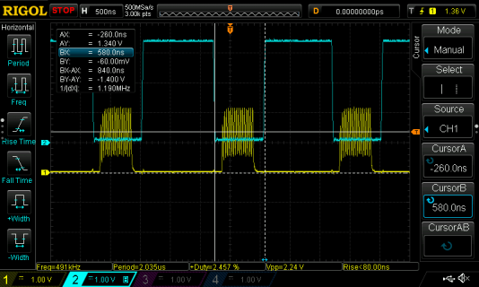
with scope i see 500 KHz sample rate, duration of CS LOW event is 840 ns (blue). SPI CLK (yellow) is 30 mhz, and 16-bit transfer takes 533 ns.
(it works for measurement purposes with no SPI device attached)
spiadc.png

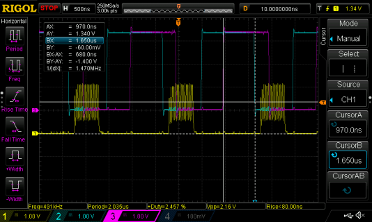
The ISR latency from when PWM (purple) goes high til CS (blue) is pulled low is about 680 ns, so a sample takes about 1.51 us, and max sample rate would be 667 KHz.
spipwm.png

comparisons with Arduino 1.8.8 and 1.47 beta4
Code:
T3.5@120mhz SPI 30 mhz  CS low 824 ns, ISR 700 ns, total 1.53 us  (max 654 Ksps)
T3.6@180mhz SPI 30 mhz  CS low 788 ns, ISR 480 ns, total 1.28 us  (max 781 Ksps)
T4B2@600mhz SPI 37.7mhz CS low 736 ns, ISR 220 ns, total 0.96 us  (max 1.04 Msps)
 
Last edited:
Many thanks, that looks perfect.

LTC2327-16 is the ADC. It's pretty decent. There isn't a CS as such used, 'cnv' initiates a conversion and 'BUSY' is an indicator to start clocking the data out.

I'll test this when back in on Monday with the full system and let you know how it goes.
 
Status
Not open for further replies.
Back
Top