USART on Teensy 3.2

Status
Not open for further replies.

xp677

Member
Hi all,

I'm currently working on a project in which I'm trying to communicate with a motor control unit over what appears to be a unique protocol.

I've made a long post on my progress in a thread here: https://openinverter.org/forum/viewtopic.php?f=14&t=205

To summarise, this unit is designed to receive a constant 500KHz clock, and will output a 100-byte packet of information whenever its request pin is pulled low.

The data contains start and stop bits, the format is 0 xxxxxxxx 1.

I've been advised that this is a synchronous UART format.

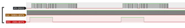
I've attached some pictures below, showing the waveforms from a logic analyser connected to the unit (clock and request signals provided by a benchtop function generator).

A typical packet looks like below:


Each "byte" has a start bit, 8 data bits, and a stop bit, as below:


An overview of the data received.


A close-up of the start of each packet


A close-up of the middle of each packet, where things are more interesting than "00000000"


Note that this is a differential signal, it is likely inverted, so the 1 11111111 0 you see in the first packet is actually "0 00000000 1". I am not using a differential transceiver right now, although I do have one on the way.


I believe that for USART communication, a pin must be defined to act as a clock generator, and that TX and RX will sync to this pin. I'm not sure how to implement this on Teensy. There are a few forum thread on the Arduino forum where this has been achieved, but I fear that it may be microcontroller specific, and would not apply to the Teensy.

The final goal is to be able to write to this device as well, this is done over a separate pin, and again is a synchronous UART stream in teh same format as the one I'm trying to read.

Any advice would be greatly appreciated!
 
To summarise, this unit is designed to receive a constant 500KHz clock, and will output a 100-byte packet of information whenever its request pin is pulled low.

I'd start by trying analogWriteFrequency() and analogWrite() to create a 500 kHz 50% duty cycle waveform for the needed clock.

Looks like the data format might "just work" with ordinary Serial1 if you set the baud rate with Serial1.begin(500000), and use digitalWrite on another pin to give it the pulse to request data output.
 
Hi Paul,

This is uncanny! I had literally just finished writing code to that effect!

Code:
#define cs_pin 6
// serial 3 rx 7
// serial 3 tx 8
#define clock_pin 10

//definitions
#define inverter_msg_length 100

//global variables
int inverter_msg[inverter_msg_length]={0};
int inverter_byte=0;

void setup() {
  Serial.begin(9600);
  Serial3.begin(250000);
  
  pinMode(cs_pin, OUTPUT);
  pinMode(7,INPUT):

  analogWriteFrequency(clock_pin, 250000);
  analogWrite(clock_pin, 127);

  delay(100);
}

void loop() {

  digitalWrite(cs_pin, 1); //send request

  Serial.println("Start of transmission.");

    inverter_byte=0;
    while(Serial3.available()) {inverter_msg[inverter_byte] = Serial3.read(); inverter_byte++;}
  
  delay(1); //just for now, to hold the REQ line high
  digitalWrite (cs_pin, 0);
  Serial.println("End of transmission.");

//print results
  Serial.println("\t0\t1\t2\t3\t4\t5\t6\t7\t8\t9");
  Serial.println("   ------------------------------------------------------------------------------");  
  for (int j=0;j<10;j++)  {                             //print 10 rows
    Serial.print(j*10);if(j==0)Serial.print("0");Serial.print(" |\t");              //row heading 
    for (int k=0;k<10;k++){Serial.print(inverter_msg[j*10+k]);Serial.print("\t");}       //print 10 columns of data
    Serial.print("\n");
  }

  delay(500);
}

I've set it at 250KHz for now, as I wasn't sure of the capability of the UART on the Teensy. I was just compiling this when I got the notification of your reply. Now time to try it out! :)
 
Last edited:
Sorry, I don't have much insight here, maybe others might.

But if it were me, some of the steps I might try include:
a) Hook it up to something like a logic analyzer and or Oscilloscope and check to see what Baud rate it is using. That is assuming you don't already know this.

b) Experiment with some of the SerialX format options. Like Serial1.begin(115200, SERIAL_8O1_RXINV);
I don't give this much hope of working as...

c) Looking at one of your images, it shows, the input as MISO - Master In Slave Out - SPI communications, not Serial (UART).
Again the question is, how accurate is that REQ pin. As it looks like it sort of acts like a Chip Select pin(CS) for SPI, but if so it should stay high during the transfer of the bytes of the packet. (Looks like CS is inverted... from simple/standard SPI, but there are modes you can set.

So again to me this looks more like an SPI slave like operation. The main SPI library on Teensy is for master, but there are threads that talk about how to do slave.

Hope that helps some, in maybe looking more into what the exact data format is.

Good luck
 
Hi Kurt, thanks for the reply.

To answer your points:

a) The waveforms in my post above are from ym logic analyzer. The CLK is a 500KHz wave, so I guess 500KHz. I have played around with the frequency of this, and the frequency of the serial data received does change to suit. It seems that we can set the baud rate using the CLK line.

c) I named in MOSI, back when I thought this was SPI. Now I don't believe the same, hence the later picture have it labelled as "data" ;).

The req pin is a 1ms pulse, repeated every 4ms, so a 250Hz square wave at 25% duty cycle. In reality, any change in this will trigger a whole 100-byte packet to be sent. I can leave it high for the duration of a transfer, the unit won't mind, and it will wait for another rising edge before it will transfer again. alternatively, I can send a single pulse and the transfer will still complete.

I tried using SPI on the Teensy, but I encountered the following issues:

From what I've seen/read online about SPI, it seems that SPI does not use start and stop bits. Also, SPI only transmits clock pulses as data is being requested. This unit accepts a "constant" clock, and outputs a 100 x 10-bit packet each time the REQ line is triggered. The clock runs constantly throughout. I also noticed that if the clock stops momentarily, the data keeps flowing without a clock pulse.

Because of this, I cannot read this as a SPI signal. My attempts to use a microcontroller set to transmit/receive SPI result in the microcontroller outputting 8 clock pulses, then a brief pause, then another 8 clock pulses, etc. This results in data being received, but the data is corrupt - the microcontroller just receives what was being sent at the time it attempted to read from the inverter.

Another interesting thing is that the inverter board waits for 39 clock pulses after receiving a REQ pulse, and starts to output on the 40th pulse.

I'll look into your point b) about options for the serial ports.
 
I'd start by trying analogWriteFrequency() and analogWrite() to create a 500 kHz 50% duty cycle waveform for the needed clock.

Looks like the data format might "just work" with ordinary Serial1 if you set the baud rate with Serial1.begin(500000), and use digitalWrite on another pin to give it the pulse to request data output.

Hi Paul,

I tried your method using the code I posted above, this does cause the unit to generate packets of data as expected, however the Teensy does not seem to be accepting them.

I am using serial 3, with the communication coming in on pin 7. I had to set pinMode(7,INPUT);, as it appeared to be puling down the data stream otherwise.

A cut down of my code for examination would be something like:

Code:
#define cs_pin 6
// serial 3 rx 7
// serial 3 tx 8
#define clock_pin 10


int inverter_msg[100]={0};
int inverter_byte=0;

void setup() {
  Serial.begin(9600);
  Serial3.begin(500000);
  
  pinMode(cs_pin, OUTPUT);
  pinMode(7,INPUT):

  analogWriteFrequency(clock_pin, 500000);
  analogWrite(clock_pin, 127);

  delay(100);
}

void loop() {

  digitalWrite(cs_pin, 1); //send request

  inverter_byte=0;
  while(Serial3.available()) {inverter_msg[inverter_byte] = Serial3.read(); inverter_byte++;}
  
  delay(1); //just for now, to hold the REQ line high
  digitalWrite (cs_pin, 0);

  for (int i=0;i<100;i++){Serial.print(inverter_msg[i]);Serial.print(",");}
  Serial.print("\n");
  }

  delay(500);
}

The main line of code here is:

while(Serial3.available()) {inverter_msg[inverter_byte] = Serial3.read(); inverter_byte++;}

I would have expected this to populate the 100-long array with the data stream, however when printing this to Serial(USB), I get all 0's.

I guess my real question is whether it is possible to configure any of the UARTs on the Teensy to run as a syncronous master, i.e. to have them generate a clock and read/write in time with that clock. Using a SPI library brings up the limitations in my post above, with regards to start/stop bits, breaks in the clock pulses when using SPI, and a delay in this unit outputting the first bits of data.
 
Last edited:
No, do not use pinMode(). Serial3.begin() configures the pin. Using pinMode() reconfigures the pin for GPIO control, which effectively takes it away from Serial3. Delete that pinMode() line.
 
Yes, removing pinMode() sorted this. I am now receiving the data.

However, I'm not quite getting what I expect! The data generally follows what I've previously seen on a logic analyzer, however it doesn't seem to show the full packet.

I have tried playing with the serial modes, it seems that the code will only compile with 8E1, 8O1, or 8N1. All give slightly different results, but none of them have fixed this issue.

Two things it may be:

1. The PWM may not be 100% synchronous to the serial port. If there is a slight difference in the baud rate compared to the PWM frequency, would this cause the issue I'm seeing?
2. Is Serial.available() stopping at a certain point? I receive 63 bytes of data, out of 100. The process is "ending" at the large block of zeros which appear in the second half of this packet. On the analyzer, the start adn stop bits are still transmitted, so I imagine that if they were being parsed correctly, the UART would recognise these zeros and keep on processing?

Hopefully this picture helps make things clear! The paper printout is a printout of a typical packet from this unit. Note that the "random" values do change, I'd expect them to be different, however most of the single-bit values (1,4,32,255, etc) don't change between packets. It is these that I am using to verify that the transmission is being correctly received.

Click for big:

 
My guess is that your code is busy in you inner loop while the Serial3 characters arrive and if you look at
...\cores\teensy3\serial3.c you will see: #define SERIAL3_RX_BUFFER_SIZE 64 // number of incoming bytes to buffer


So the buffer is 64 bytes long and it will toss anything else it receives...

Obviously there are a few different ways to fix this:

a) edit serial3.c change this size > 100

b) Change your code as to not get into this condition...


Or it may be due to your initial code, that is:
The code in your loop:

Code:
;
  while(Serial3.available()) {inverter_msg[inverter_byte] = Serial3.read(); inverter_byte++;}

Again will only read in what is currently queued up in the buffer as mentioned. Your code could instead be setup, that when you start to receive a packet, you can continue to read and fill in your array and exit after the appropriate bytes have been read or a timeout...

Or you could simply use the Arduino function for this(https://www.arduino.cc/en/Serial.ReadBytes): inverter_byte = Serial3.readBytes(inverter_msg, 100);

And you can set the timeout...

Or you could try it something like:
Code:
#define cs_pin 6
// serial 3 rx 7
// serial 3 tx 8
#define clock_pin 10


int inverter_msg[100]={0};
int inverter_byte=0;

void setup() {
  Serial.begin(9600);
  Serial3.begin(500000);
  
  pinMode(cs_pin, OUTPUT);
  pinMode(7,INPUT):

  analogWriteFrequency(clock_pin, 500000);
  analogWrite(clock_pin, 127);

  delay(100);
}

void loop() {
  elapsedMicros em = 0;  // simple timer... 

  digitalWrite(cs_pin, 1); //send request

  inverter_byte=0;
  while ((em < 1000) {  // wait one ms and process all bytes that come in...
    if (Serial3.available()) {inverter_msg[inverter_byte] = Serial3.read(); inverter_byte++;}
  }
  digitalWrite (cs_pin, 0);

  // Hopefully receive the remaining bytes within lets say 100ms...
  // for the rest of your message 100 bytes?
  while ((em < 100000) && (inverter_byte < 100)) {
    if (Serial3.available()) {inverter_msg[inverter_byte] = Serial3.read(); inverter_byte++;}
  }
  // now print out your stuff.
  for (int i=0;i<100;i++){Serial.print(inverter_msg[i]);Serial.print(",");}
  Serial.print("\n");
  }
  // delay the number of ms left in your cycle
  delay(500 - (em/1000);
}

Again there maybe issues...
 
Status
Not open for further replies.
Back
Top