sniper1rfa
Member
Long story short, I am in a position where I need to intercept a ~100 line hall effect magnetic encoder, and scale it to a ~40 line VR sensor. I'd like to get some advice on the best way to proceed.
For reference, the hall is obviously digital, and the VR sensor is a roughly-sinusoidal voltage source where the negative zero-crossing is the critical piece of information.
Encoder RPM will be up to 1200RPM, so the output signal will vary between ~40Hz and 1kHz (approximate min, absolute max), and the input will be about twice that.
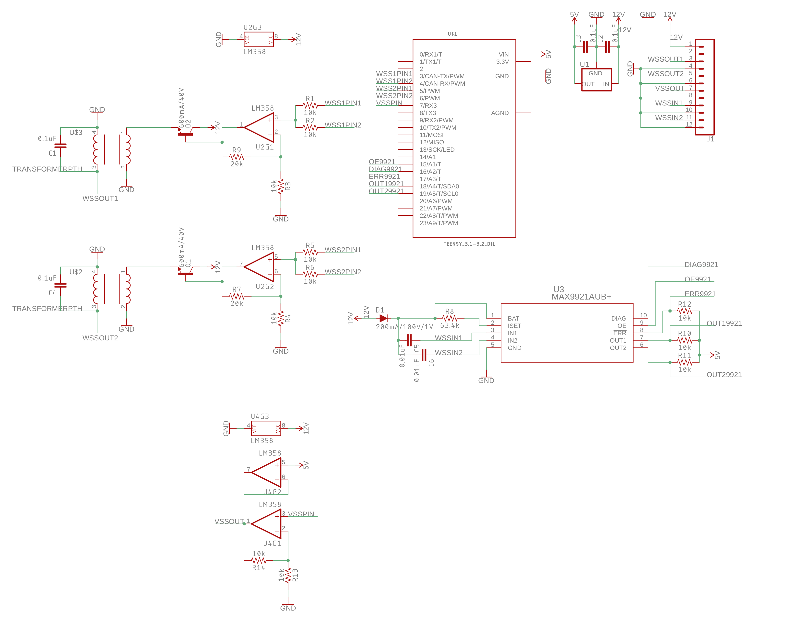
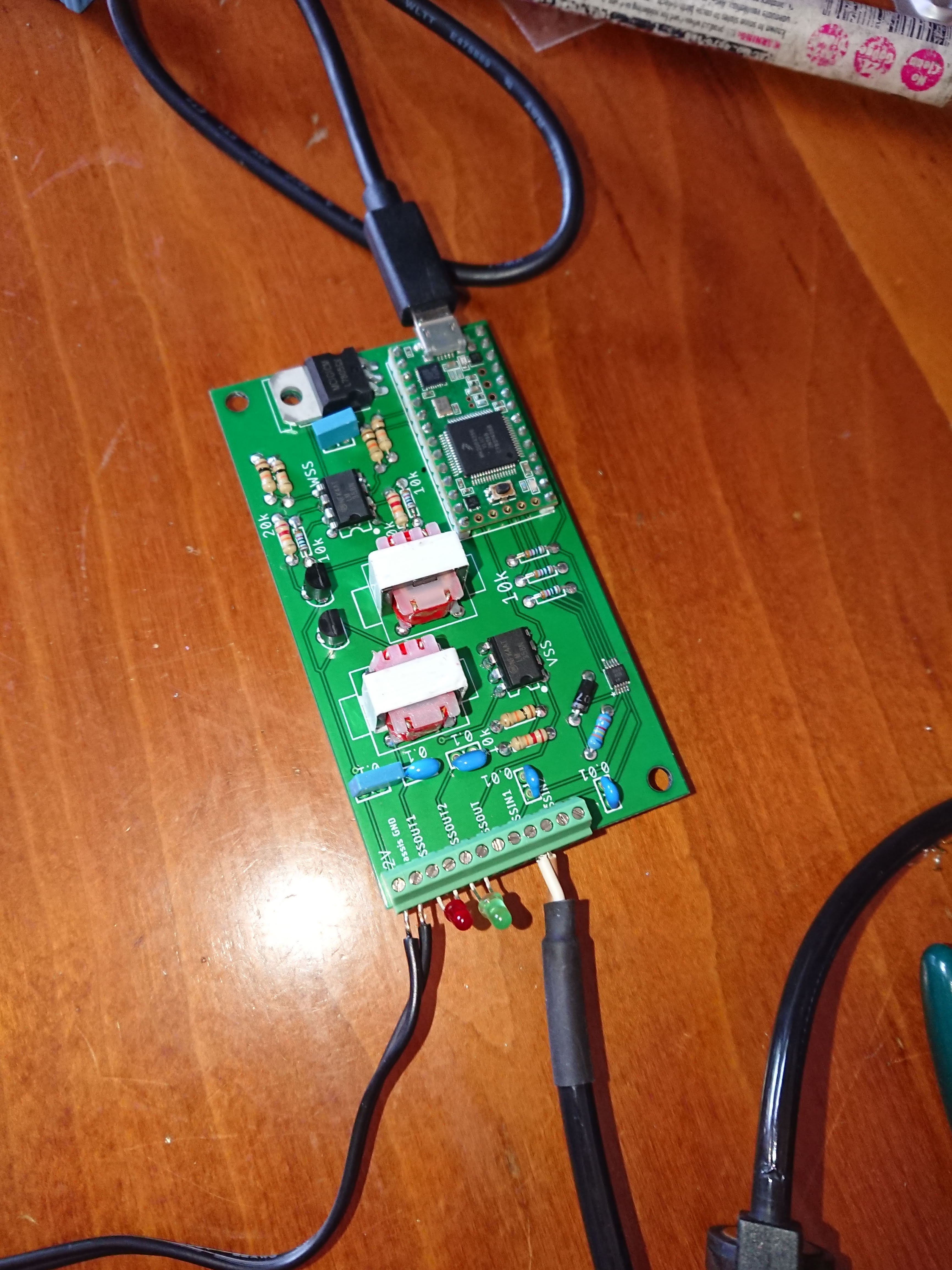
The current plan is to use a MAX9921 hall interface to produce a clean digital signal from the hall, then run that into an interrupt to get timing information. I intend to use a reasonably fast complementary filter to produce a stable 'current pulsewidth' value, multiply that value by the correct scaling factor, and use the scaled pulsewidth to produce an analog output. Analog out -> op-amp -> transformer -> VR sensor interface.
I'm not a software guy, so i am hoping for some advice on which of the following (or some other thing) would be the best way to approach the problem.
1. Digital. There is some evidence (http://publications.lib.chalmers.se/records/fulltext/219351/219351.pdf) that using two summed digital outputs (giving three possible outputs of 0, 1/2, and 1) run through a transformer is good enough. However, there seems to be an assumption that the output of the transformer described in the paper matches the input, but I'm under the impression that a digital signal of any kind sent through a transformer will come out the other end as simple pulses, which means you're going to end up with a lot of possible false zero-crossings. Since I plan to use this in real operation, I'd like to avoid that.
2. Create a simple output waveform (triangle or sinusoidal) based on timers and a lookup table, using the pulsewidth value to modulate the time between each step. Two problems, I think, with this approach are that low frequencies and high frequencies will contain the same number of steps, leading to a low frequency limit where the xformer output will decay into discrete pulses, and a high frequency limit based on clock speed and the chosen timing resolution. Advantage is that the code is simple and approachable, and there is good visibility into exactly what's happening. Conceptually, this approach also has a very low latency between the input and the output (which is important but not critical).
3. Create a waveform using the audio library, and modulate *that* with the pulsewidth value. Advantage is obviously that it's relying on tested code that clearly produces high quality waves, at the expense of visibility into the inner workings. For example, will the output of a pitch change be reasonably differentiable, or will it have a discontinuity? What is the pitch resolution of the audio library around to 100-200Hz range? 1khz? What is the actual latency I could expect?
Any help would be greatly appreciated.
For reference, the hall is obviously digital, and the VR sensor is a roughly-sinusoidal voltage source where the negative zero-crossing is the critical piece of information.
Encoder RPM will be up to 1200RPM, so the output signal will vary between ~40Hz and 1kHz (approximate min, absolute max), and the input will be about twice that.
The current plan is to use a MAX9921 hall interface to produce a clean digital signal from the hall, then run that into an interrupt to get timing information. I intend to use a reasonably fast complementary filter to produce a stable 'current pulsewidth' value, multiply that value by the correct scaling factor, and use the scaled pulsewidth to produce an analog output. Analog out -> op-amp -> transformer -> VR sensor interface.
I'm not a software guy, so i am hoping for some advice on which of the following (or some other thing) would be the best way to approach the problem.
1. Digital. There is some evidence (http://publications.lib.chalmers.se/records/fulltext/219351/219351.pdf) that using two summed digital outputs (giving three possible outputs of 0, 1/2, and 1) run through a transformer is good enough. However, there seems to be an assumption that the output of the transformer described in the paper matches the input, but I'm under the impression that a digital signal of any kind sent through a transformer will come out the other end as simple pulses, which means you're going to end up with a lot of possible false zero-crossings. Since I plan to use this in real operation, I'd like to avoid that.
2. Create a simple output waveform (triangle or sinusoidal) based on timers and a lookup table, using the pulsewidth value to modulate the time between each step. Two problems, I think, with this approach are that low frequencies and high frequencies will contain the same number of steps, leading to a low frequency limit where the xformer output will decay into discrete pulses, and a high frequency limit based on clock speed and the chosen timing resolution. Advantage is that the code is simple and approachable, and there is good visibility into exactly what's happening. Conceptually, this approach also has a very low latency between the input and the output (which is important but not critical).
3. Create a waveform using the audio library, and modulate *that* with the pulsewidth value. Advantage is obviously that it's relying on tested code that clearly produces high quality waves, at the expense of visibility into the inner workings. For example, will the output of a pitch change be reasonably differentiable, or will it have a discontinuity? What is the pitch resolution of the audio library around to 100-200Hz range? 1khz? What is the actual latency I could expect?
Any help would be greatly appreciated.