T4 and Peripheral Clock adjustments

Status
Not open for further replies.

TelephoneBill

Well-known member
When measuring the output frequency of a QTIMER on a T4, I found it to be 5ppm slow on the theoretical value. This will be attributable to the 24 MHz oscillator also being 5ppm slow (within spec and temperature related).

To try compensate, I have been experimenting with ideas to FINE control the T4 peripheral clock. I did try adjust the bias current for XTALOSC24M_MISC0, but I could not see any appreciable osc frequency change over the programmable range. Certainly not of ppm size.

So the next idea is to synthesize the output frequency by changing the COMPARE value at infrequent intervals, in order to "drop" a 6.7 nS (one 150 MHz clock pulse) period, and thereby speed up the QTIMER output by a predictably small amount. But this is a bit of a coarse method.

But before I take this approach, I wondered if there was any (possibly non documented) ways to "nudge" the 150 MHz peripheral clock frequency by fine amounts?

Lastly, where can I download a spec from the web for the 24 MHz crystal module? Thanks for any info...
 
I don't know the part number for T4 crystals or how to adjust the 24mhz for the QTIMER, but of course crystal frequency changes with temperature and each T4 crystal could have a different frequency offset. Here are the crystal offsets for the T4's I have known :)
https://forum.pjrc.com/threads/54711-Teensy-4-0-First-Beta-Test?p=195166&viewfull=1#post195166
I don't think there are any configurable internal capacitance values. During early beta testing, i think Paul experimented with various capacitors for the 24mhz crystal.
https://forum.pjrc.com/threads/54711-Teensy-4-0-First-Beta-Test?p=195206&viewfull=1#post195206
 
Last edited:
Thanks for your useful response. I have just been doing some more experiments with T4 and have further very good results which may be of interest. Appreciate that temperature is a key factor - and more of this in a moment.

The experiments used the technique to infrequently "drop" a 6.7 nS clock pulse inside the timer ISR. I do this for COMP10. My output test frequency is 100 KHz and I use a GPS 100 KHz as a scope reference, looking for any display drift of the T4 signal. The "half period" (Mark period) has to be 5uS for 100 KHz so I use the value 750 clocks (each clock being nominally 6.666...nS) to get 5uS. The COMP10 value is 750 - 1 = 749 (which you kindly pointed out some while back).

When cold, the COMP10 value is set to change from 749 to 748 at intervals of "202 cycles" of the ISR. But as this warms up, I can manually change the switch interval to be a bit more frequent (typing C200, C199 etc using the serial monitor). For my crystal, this has come down to "126 cycles" over a period of 20 minutes or so. I post the code for this attached if anyone wants to play.

The results of this "drop 1 cycle" technique have proven to be much better than I expected in reality. I can get the signal "stationary" on the scope for very long periods (eventually it will drift due to temperature changes).

Now I can also manually type "D0", "D2", "D4", or "D6" to alter the bias current to the 24 MHz crystal oscillator. Much to my surprise, this now has a very useful effect when the drift has been slowed to such an extent described.

Back to the temperature issue, maybe another technique could help stabilise temperature. If the crystal was in contact with a heat source, then controlling the heat source could be a viable compensation method. I did wonder if the on-board LED could be thermally coupled to the crystal and then pulse the LED to effectively control the crystal temperature. Something to consider for another experiment. This is why I am interested in the crystal spec to see if this can be "elevated" safely.

Code:
//TestT4009 - QTIMER TEST PROGRAM for T4
//======================================
//Author: TelephoneBill
//Date: 17 AUG 2019
//Version: 001

//NOTES: Using QT3 Timer0 as timer - fine frequency control of 100 KHz output.
//Use serial monitor command "Cxyz<CRLF>" (e.g. where xyz = 202) to adjust rate at which COMP10 is switched from (750-1) to (750-2).
//Lower values of "xyz" will speed up the 100 KHz output waveform. Higher values slow it down.
//Use serial monitor command "Dx<CRLF>" where x = 0, 2, 4, 6 - to alter XTALOSC24 bias current (Nominal, -12.5%, -25%, -37.5%).

//definitions
byte Byte1, Byte2, Byte3, Byte4;
volatile uint32_t ISRTicks, BiasValue, Bias, Comp10Val;


//SETUP
//=====
void setup() {
  //initialise general hardware
  Serial.begin(115200);                 //setup serial port
  pinMode(13, OUTPUT);                  //pin 13 as digital output
  FlashLED(4);                          //confidence boost on startup
  
  //enable clocks for QTIMER3
  CCM_CCGR6 |= 0xC0000000;              //enable clocks to CG15 of CGR6 for QT3

  //configure QTIMER3 Timer0
  TMR3_CTRL0 = 0b0000000000000000;      //stop all functions of timer 
  TMR3_SCTRL0 = 0b0000000000000001;     //b0=1(OFLAG to Ext Pin)
  TMR3_CNTR0 = 750-1;                   //6.666666 nS per clk, 750 times clks = 5uS (half period for 100 KHz)
  TMR3_LOAD0 = 0;
  TMR3_COMP10 = 750-1;
  TMR3_CMPLD10 = 750-1;
  TMR3_COMP20 = 750-1;
  TMR3_CMPLD20 = 750-1;
  TMR3_CSCTRL0 = 0b0000000010001001;    //b7=1(CMP2 interrupt enabled), b32=10(preload CMP2 from CMPLD2), b10=01(preload CMP1 from CMPLD1)
  
  //configure Teensy pin Compare outputs
  IOMUXC_SW_MUX_CTL_PAD_GPIO_AD_B1_00 = 1;      // QT3 Timer0 is now on pin 19

  //enable QT3 interrupt within NVIC table
  attachInterruptVector(IRQ_QTIMER3, QT3_isr);  //declare which routine performs the ISR function
  NVIC_ENABLE_IRQ(IRQ_QTIMER3);

  //initialise variables
  ISRTicks = 0;
  Comp10Val = 202;

  //start the timers
  TMR3_CTRL0 = 0b0011000000100100;      //CM=001,PCS=1000,LENGTH=1,OUTMODE=100
}


//ISR ROUTINE FOR QT3
//===================
//FASTRUN puts this code into RAM
FASTRUN void QT3_isr(void) {
  //reset any interrupt flags
  TMR3_CSCTRL0 &= ~(TMR_CSCTRL_TCF1|TMR_CSCTRL_TCF2); //reset compare flags
  ISRTicks++;
  if (ISRTicks>=Comp10Val) {
    ISRTicks = 0;
    TMR3_CMPLD10 = 748; //(750-2)
  }
  else {
    TMR3_CMPLD10 = 749; //(750-1)
  }
  asm volatile("dsb");                  //ensure memory synch
}


//MAIN LOOP
//=========
void loop() {
  //call KeyInput() routine
  KeyInput();
}

//SUBROUTINES
//===========
//Flash LED routine
void FlashLED(int m) {
  for (int n=0;n<m;n++) {
    digitalWriteFast(13, 1);          //set pin 13 high
    delay(100);
    digitalWriteFast(13, 0);          //set pin 13 low
    delay(100);
  }
}

//KeyInput routine
void KeyInput() {
  //process any keystrokes available
  if (Serial.available()>0) {
    //read the incoming byte
    Byte1 = Serial.read();
    if (Byte1>0x20) {
      switch (Byte1) {
      case 'D':  //bias drive value
        //task goes here...
        if (Serial.available()>=3) {
          Byte2 = Serial.read();
          BiasValue = Byte2-0x30;
          Bias = BiasValue << 12;
          XTALOSC24M_MISC0 = (XTALOSC24M_MISC0 & 0xFFFF9FFF) | Bias;
        }
        Serial.print("Bias = "); Serial.println(Bias);
        break;
      case 'C':  //'mark' value adjustment interval
        //task goes here...
        if (Serial.available()>=5) {
          Byte2 = Serial.read();
          Byte3 = Serial.read();
          Byte4 = Serial.read();
          Comp10Val = ((Byte2-0x30) * 100) + ((Byte3-0x30) * 10) + ((Byte4-0x30) * 1);
        }
        Serial.print("Comp10Val = "); Serial.println(Comp10Val);
        break;
      }
    }
  }
}
 
Last edited:
Very interesting! I just got my T4, which I guess is from the second batch, and tried out this program. I put the T4 pin 19 on one scope channel, and my GPSDO 10 MHz output on the other. Looks like my particular T4 board needs "C080" or Comp10Val = 80 to be nearly in sync with the frequency standard. With C079 the waveform drifts the opposite way. However it is temperature sensitive enough that even briefly putting my finger on the board makes it drift the opposite way for a while, until the temperature equilibrates again. Also, a few seconds of breathing on it makes a big difference, requiring C082 or so to balance out. My office is around 24 C at the moment.
 
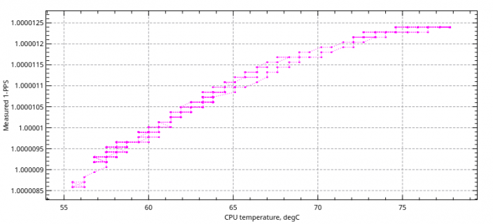
frequency vs temperature

With my office ambient temperature around 23 C, my T4 running a simple FreqMeasure test reports itself at T= 56 C after some time to equilibrate, and its clock runs 9 ppm slow relative to my 1-PPS standard. It gets slower at warmer temperatures, with a tempco around -0.24 ppm/C. I notice my particular T4's tempco drops to near zero with F = -12.5 ppm, at a reported CPU temperature of 77 C. However I don't know how hot the T4 board can safely be run. Below graph is from a 12 hour run with one temperature cycle, starting at CPU = 55 C, going up to 78 C and then back to 57 C. (The graph is rising with temperature because it is the measured frequency of an accurate 1-PPS input signal, so the higher reported value means the T4's internal clock is running slower.)
190818-T4-freq.png
 
Last edited:
@JBeale

The max temp before auto shutdown is 90C. It can be run hotter if you change that setting in the tempmon.c file in the core.
 
Status
Not open for further replies.
Back
Top